


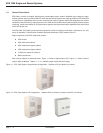
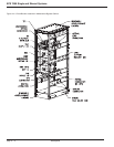

1.4.5 Mechanical Considerations
The EPS 7000 can be mounted on a raised floor, or flush-mounted on a concrete floor. All floors must be level. The
conduits are landed on a panel located on left top panel of the module as shown on the installation drawings. On
a raised floor the unit can be equipped with an optional auxiliary cabinet to allow conduits to be run below the floor.
Battery cabinet(s) may be placed adjacent to the UPS module on the right side (when viewed standing in front and
facing the module), or may be installed as stand-alone cabinets. Auxiliary cabinet(s) are placed to the left of the UPS
module.
Floor loading must be considered when installing an EPS 7000 system on a raised floor or on an upper story of a
multiple-story building. Floor loading data is provided on the installation drawings supplied with the equipment.
Consult a structural engineer while planning your EPS 7000 UPS installation.
After installation, the EPS 7000 module requires a minimum of 1 meter (36 inches) front and top clearance for
normal maintenance. Side or rear access is not required.
IMPORTANT: Side or rear access may be required for installations where
cable restraints are necessary.
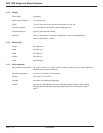
1.4.6 Electrical Considerations
Electrical service for the EPS 7000 system should be supplied on its own dedicated branch circuit. Main input
cables, upstream protective devices, and downstream protective devices must be provided and sized per the
National Electrical Code (NEC) requirements, per local codes as applicable, and as appropriate for your load and
distribution requirements. Recommended cable sizes and UPS ratings are provided on the installation drawings.
The EPS 7000 is a separately-derived source.
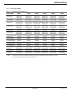
1.5 UPS Single Module and Shared System Specifications
Specifications provided refer to an EPS 7000 module and any required auxiliary cabinets.
Introduction
EPS 7000 Single and Shared Systems
page 1 — 4