


EPS 7000 Single and Shared Systems
page 2 — 6
Description
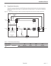
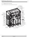
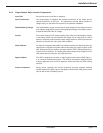
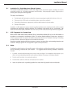
2.1 Shared System Description
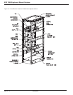
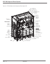
This section describes the shared system in detail, including single line diagrams, rating and component locations.
See Shared Systems, Users Manual 86-134005-00 for operation.
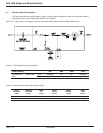
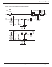
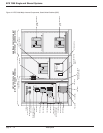
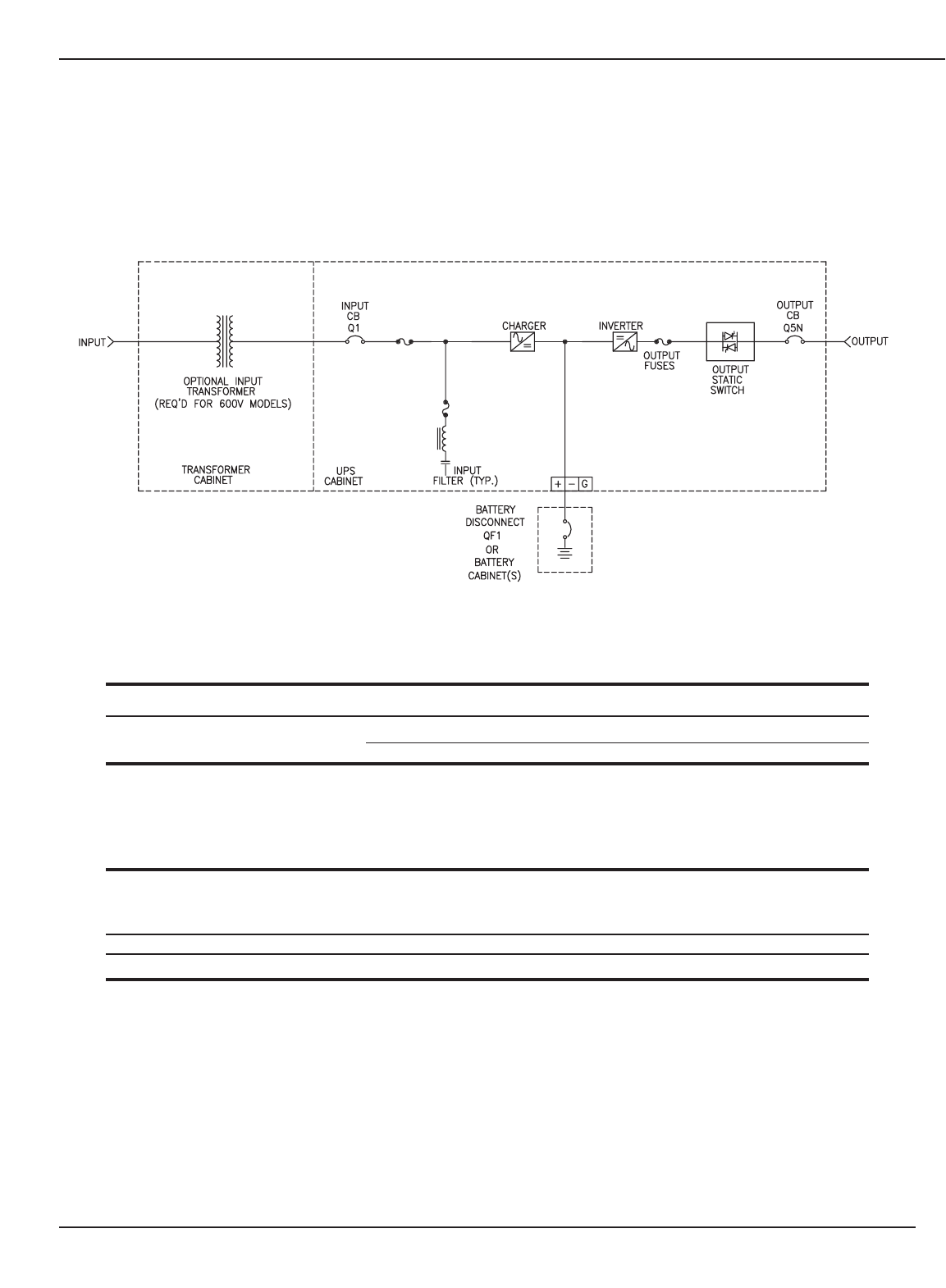
Figure 2-4: Typical Single Line Diagram, (480 VAC Input/Output Multi-Module UPS with Battery Disconnect.)
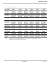
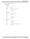
Table 2-2: EPS 7000 Shared Systems Ratings
WEIGHT (LBS/KG) UPS MBP XFMR TOTAL
300/400/500 kVA Shared system 480V 6,800/3,090 NA OPT 6,800/3,090
60hz 600V 6,900/3,130 NA 3,600/1,640 10,500/4,770
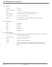
Table 2-3: Model Number, Static Switch Cabinets (SSC)
INPUT OUTPUT INPUT TOTAL TOTAL HEAT
VOLTAGE VOLTAGE CB WIDTH WEIGHT LOSS
(VAC) (VAC) (Amps) (mm/in) (kg/lb) (Btu/hr)
480 480 4000 Max 1829/72 1317/2900 (Negligible)
600 600 4000 Max 1829/72 1317/2900 (Negligible)