


Always “On” UPS Systems Inc.
7
Presentation
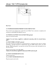
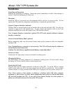
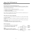
Front Panel
1. POWER bar graph (BATTERY CHARGE/LINE VOLTAGE)
This displays the present battery charge as a percentage of battery capacity. It also displays
the utility line voltage.
2. LOAD bar graph
This displays the amount of power required by the load as a percentage.
3. "OVERLOAD" indicator (RED LED)
This LED lights when the load(s) connected to the UPS exceed the UPS's capacity. See
Section 6.3 for solution to this problem.
4. "BUCK AVR (Automatic Voltage Regulation)" indicator (YELLOW LED)
This LED illuminates when the UPS is correcting for a high utility voltage condition. The
load(s) receive normal 120VAC power.
5. "ON/TEST" button
With the UPS plugged in, press the ON/TEST button to turn on the UPS and power the loads.
ON/TEST also activates the UPS's self-test and utility line voltage displays.
6. "LINE NORMAL" indicator (GREEN LED)
This LED illuminates when the line input voltage is normal.
7. "OFF" button
Press the OFF button to turn off the UPS and the load(s).
8. "BACK UP" indicator (GREEN LED)
This LED illuminates when the UPS is supplying battery power to the loads.
9. "BOOST AVR (VOLTAGE BOOST)" indicator (YELLOW LED)
The LED illuminates when the UPS is correcting for a low utility voltage condition. The
load(s) receive normal power.
10. "REPLACE BATTERY" indicator (RED LED)
This LED illuminates when the UPS's batteries are no longer useful and must be replaced.
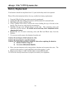
Note: When replacing the batteries, disconnect the utility power then open the case. Take
notice of the polarity before installing the new batteries to avoid a short.