


OM-884 Page 10
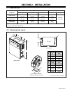
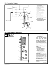
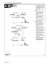
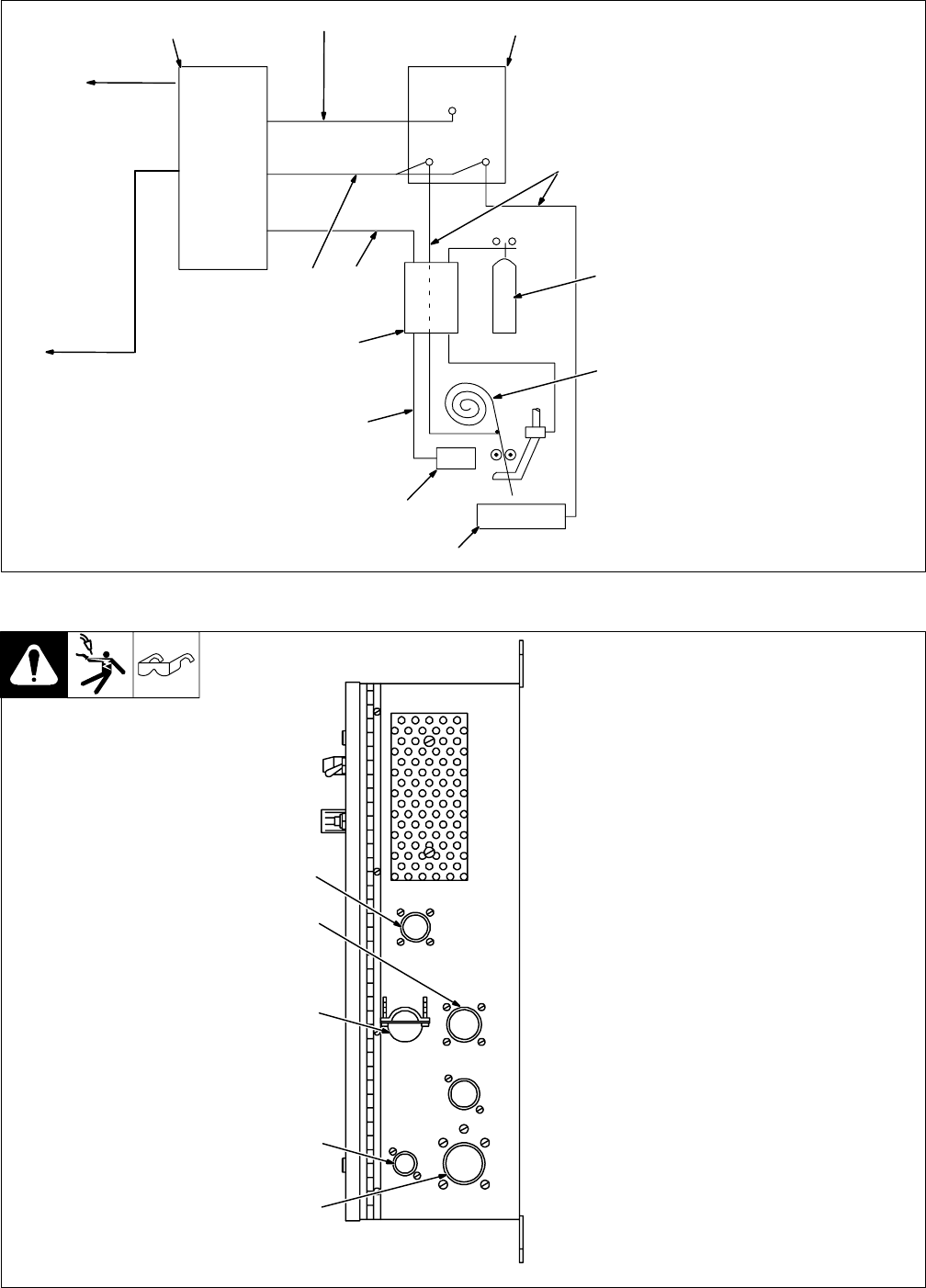
2-3. Connection Diagram
Ref. S-0290
1 Robot Interface
2 115 Volts AC/Contactor And
Output Control Cord
3 Welding Power Source
4 Weld Cables
5 Shielding Gas Supply
6 Electrode (Welding Wire)
7 Work
8 Wire Drive Assembly
9 Motor Control Cord
10 Gas Control
11 Gas Control Cord
12 Arc Sensing Cord
13 Arc Failure Connection Inside
Robot Control Unit
14 Robot Interface Connections
To Robot Control Unit
RC17
RC13
RC12
RC9
1
2
3
4
5
6
7
8
9
10
11
12
13
14
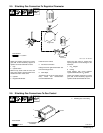
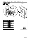
2-4. Robot Interface Connections
ST-119 646-B
1 Gas Control Receptacle RC9
2 115 Volts AC/Contactor
Control Receptacle RC13
(See Section 2-8)
Locate 115 volts ac/contactor
control cord, and connect
14-socket plug to receptacle RC13
on robot interface. To make
connection, align keyway, insert
plug, and tighten threaded collar.
Connect remaining end of cord to
Remote 14 receptacle on welding
power source.
Place welding power source
Voltage switch in Remote 14
position.
3 Strain Relief
4 Arc Sensing Receptacle
RC12 (See Section 2-7)
5 Welding Power Source
Interface Receptacle RC17
(See Section 2-9)
Obtain proper cord and 24-pin
Amphenol plug.
Connect conductors at one end of
cord to appropriate sockets in plug.
Connect plug to RC17 on robot
interface. To make connection,
align keyway, insert plug, and
tighten threaded collar.
Route and connect conductors at
remaining end of cord to robot
control unit.
1
2
3
4
5