


OM-884 Page 12
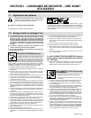
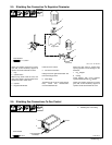
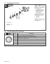
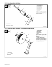
2-7. Arc Sensing Connections
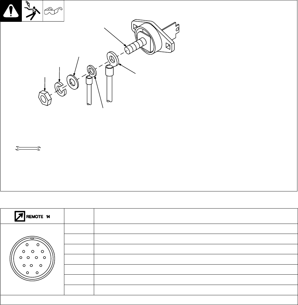
ST-121 083-A
Locate arc sensing cord, and
connect 4-socket plug to
receptacle RC12 on robot
interface. To make connection,
align keyway, insert plug, and
tighten threaded collar.
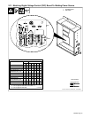
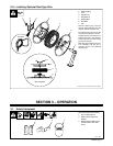
1 Positive Weld Output Terminal
On Welding Power Source
2 Weld Cable Lug Location
3 Arc Sensing Lead Ring
Terminal Location
Connect lead with ring terminal to
welding power source Positive (+)
weld output terminal as shown.
4 Flat Washer
5 Lock Washer
6 Nut
Connect lead with clamp to welding
power source Negative (–) weld
output terminal.
Tools Needed:
3/4 in
1
2
3
4
5
6
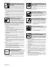
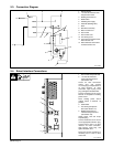
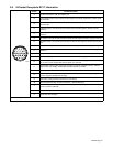
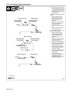
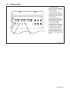
2-8. 14-Pin Receptacle RC13 Information
Pin* Pin Information
I 115 volts ac with respect to socket G. Protected by fuse F1.
J Contact closure to I completes 115 volts ac contactor control circuit.
AJ
B
K
I
G Circuit common for 115 volts AC circuit.
B
C
L
NH
C +10 volts dc input to voltage control with respect to socket D.
C
D
M
G
D Remote control circuit common.
E
F
E 0 to +10 volts dc output command signal to welding power source.
K Chassis common.
*The remaining pins are not used.