


GUIDE TO INSTALLATION AND OPERATION
8 | Kaleido K2
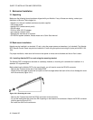
4.3.1 Connector panel installation
Remove the blank panel (a blank panel is used to occupy the rear panel space behind empty slots) or existing
connector panel. Release the captive screws at the top and bottom, and pull the panel straight out of the frame.
Slide the new connector panel into the slot on the rear of the frame. Push it gently into position until the panel is
tight against the frame and flush with the remaining panels. Fasten it into position with the captive screws at the top
and bottom. DO NOT over tighten the captive screws.
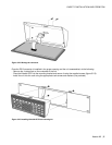
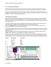
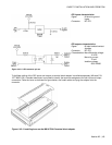
4.3.2 Module card installation
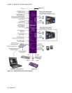
Open the front panel of the frame and locate a slot corresponding to the module. Note that a color code helps to
identify where a module should be installed (figure 4.4.2.1). All cards except the controller card are removed by
pulling up the swivel handle, which levers the card away from the mother board, and then pulling the card out of the
slot using the handle.
To install the new card, slide it into the slot, engage the swivel handle into the top panel hole and push gently on
the handle to seat the connectors into the mother board. Do not force the card into place.
Note: As the output card has an ultra-high density connector, push on the center of the front edge once it is
inserted to ensure that the connector is properly engaged.
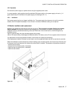
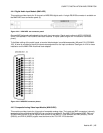
The Controller Module is a larger multi-card unit, mounted on the left side as viewed from the front. It is secured at
the bottom by a captive screw. To remove it, release the captive screw, and pull the unit out of the frame using the
aluminum bracket.
Note: Due to the weight of the Controller module assembly, you must loosen the two screws holding the rear
module - without removing it - before attempting to insert the Controller module.
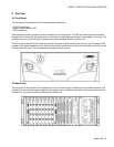
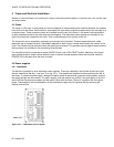
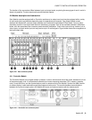
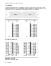
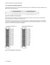
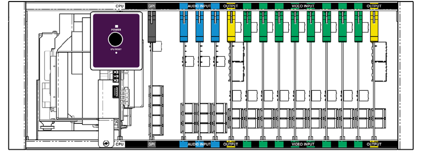
Apart from the Controller card described above, and the GPI card which is installed in the adjacent slot, all other
cards are either video input cards, audio input cards, or output cards. They fit into slots designated by type, which
are indicated by text and color along the bottom front of the frame, as follows (slot positions counted from the left):
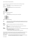
Position Module type Color Code
1 Controller White
2 GPI Grey
3 – 5 Audio input Blue
6 Output Yellow
7 – 14 Video input Green
15 Output Yellow
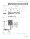
Figure 4.3.2.1 Color coding label