


GUIDE TO INSTALLATION AND OPERATION
12 | Kaleido K2
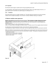
4.4.2 GPI Module
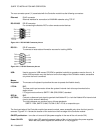
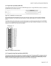
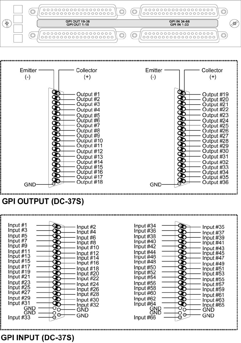
The GPI module provides interfaces and processing to support 66 contact closure tally inputs and 36 contact
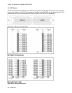
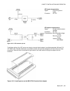
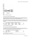
closure alarm outputs. Four DC-37S connectors are installed on the MWR-GPI rear connector panel (10). The
connector pinout and circuit schematics are shown in figure 4.4.2.2 and 4.4.2.3 respectively.
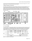
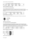
Figure 4.4.2.1 GPI rear connector panel
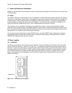
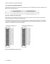
Figure 4.4.2.2 GPI connector pin-out