


8
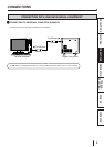
CONNECTIONS
OTHERS
PRECAUTIONS
FEATURES
PREPARATION
TROUBLE-
SHOOTING
CONTENTS
4
5
2
1
3
3
11
11
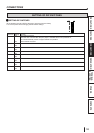
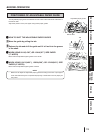
1 USB TERMINAL
Use to connect the USB cable.
See page 9.
22
22
2 DIP SWITCHES
Use to set various functions of this unit. See page 10.
SIDE AND REAR PANEL
FEATURES AND FUNCTIONS
33
33
3 HANDLE FOR TRANSPORTING
When transporting this unit, hold this handle and the upper
front part of this unit.
44
44
4 POWER SOCKET (AC LINE)
Use to connect the provided power cord. Insert the cord
firmly.
55
55
5 POWER SWITCH
Use to switch the power ON and OFF.
(LEFT SIDE)
(REAR)
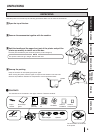
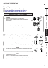
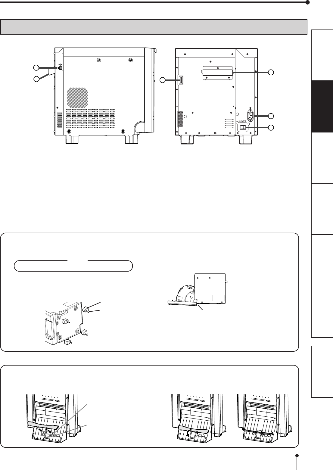
INSTALLING THE PAPER CATCHER
Hook the paper catcher by its latches. When using the print paper of 13x18(5x7”), 15x20(6x8”) or 15x23(6x9”), do not
install the paper catcher.
A. B. C.
Holes for 10 x 15 size paper
(Paper width : 152 mm)
Holes for 9 x 13 size paper
(Paper width : 127 mm)
foot
screw
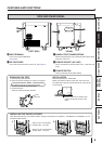
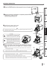
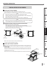
INSTALLATION
Place the printer on a stable table.
Make sure that the bottom of the door does not touch
the table when opened and that the printer does not fall
from the table.
Place the printer so that the door
does not touch the corner of the
table.
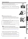
REMOVING THE FEET
1. Remove the paper strip bin.
2. Place the printer sideways as shown in the figure.
NOTE
Be careful not to get your fingers pinched.
3. Loosen 4 screws to remove the feet.
4. Raise the printer.
Keep the removed screws and feet.