


6
3.FUNCTIONS
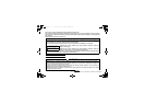
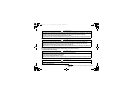
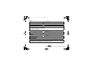
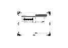
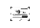
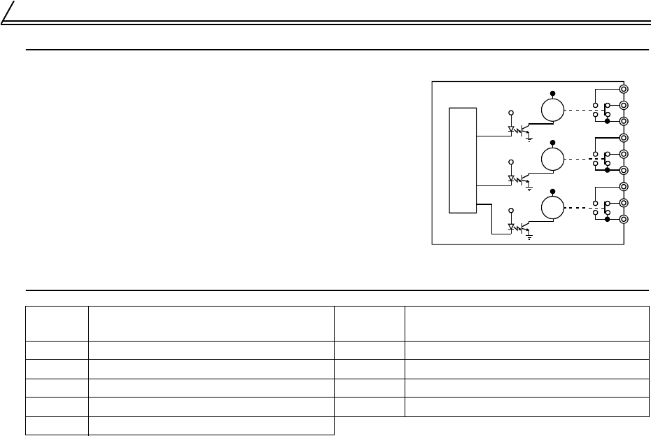
3.1 Internal Block Diagram
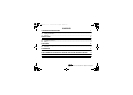
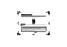
3.2 Terminals
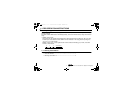
* The operation of each relay depends on the output signal selected.
You can select any three output signals available with an
inverter as standard, and output them as relay contant signals.
Functions arailable differ between FR-A500(L)/F500(L) series
and FR-V500 series.
The output signals to be selected differ according to the inverter.
Refer to the instruction manual of the inverter. (output terminal
function selection (Pr. 190 to))
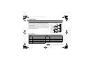
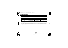
Terminal
Symbol
Description
Terminal
Symbol
Description
1A Relay RA1's normally open contact terminal 2C Relay RA2's contact common terminal
1B Relay RA1's normally closed contact terminal 3A Relay RA3's normally open contact terminal
1C Relay RA1's contact common terminal 3B Relay RA3's normally closed contact terminal
2A Relay RA2's normally open contact terminal 3C Relay RA3's contact common terminal
2B Relay RA2's normally closed contact terminal
FR-A5AR
RA1
1A
1B
1C
2A
2B
2C
3A
3B
3C
RA2
RA3
Connector
Internal circuit diagram
ib66810b.book 6 ページ 2002年2月15日 金曜日 午前8時10分
Technologies Inc.
Toll Free: voice: 1-877-539-2542 fax: 1-800-539-2542 www.mgitech.com