8
5.THE COMMERCIAL POWER SUPPLY-INVERTER SWITCH-OVER SEQUENCE FUNCTION
If the commercial power supply-inverter switch-over sequence function is activated with the FR-A5AR mounted on
the inverter, the phenomenon where magnet contactor switches alternate between ON and OFF may occur.
To prevent this, adapt either connection shown below.
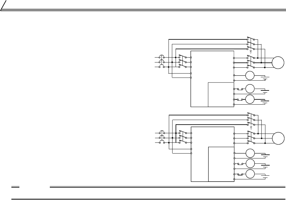
(1) Recommended connection example 1
Use inverter output terminals (Contact sig-
nal, open collector signal) instead of MG1
signals.
The phenomenon occurs when relay out-
put of the FR-A5AR is used as MC1 signal.
(2) Recommended connection example 2
When using relay output of the FR-A5AR,
set the alarm output signal (ABC) instead
of the MC1 signal and output it from con-
tacts B and C.
CAUTION
For the FR-V500 series, the commercial power supply-inverter switch-over sequence function can not be used.
IM
NFB
S1
R1
T
S
R
MC1
MC2
W
V
U
MC3
MC1
MC1
open collector
or
contacts
A and C
MC2
MC3
FR-A5AR
A
C
Supply
Motor
Inverter
MC2
A
C
MC3
IM
NFB
S1
R1
T
S
R
MC1
MC2
W
V
U
MC3
ABC
MC1
FR-A5AR
Supply
Motor
Inverter
MC2
C
MC2
MC3
A
C
MC3
B
A
C
ib66810b.book 8 ページ 2002年2月15日 金曜日 午前8時10分


