


3.1.2 Alarm Modem 56k
You find the outline of the respective variant in chapter 10.
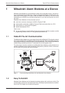
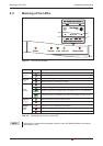
Installation and Mounting Overview of the Connectors
Mitsubishi Alarm Modem 3-2
Service
Power
Process
Line
Data out
Modem Mode
027954541034
-
+
COM2
(RS232)
COM1
(RS232)
56k
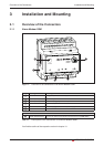
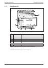
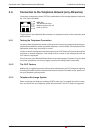
Fig. 3-2: Overview of all connectors of the Alarm Modem 56k
ᕦ
ᕥ
ᕤ
ᕣ
ᕢ
ᕡ
No. Marking Meaning
ᕡ
Line Telephone jack RJ11
ᕢ
COM1 (RS232) 9pin D-Sub jack
ᕣ
COM2 (RS232) 9pin D-Sub plug (only MAM-AM20)
ᕤ
10...30 V DC Power supply (2 screw terminals)
ᕥ
10...30 V DC Power supply (jack) for external power supply
ᕦ
Service Button
RS 485/422 with MAM-AM24
ᕣ COM2 (RS485/RS422) 5-pin screw terminal configurable over DIP switch (only MAM-AM24)
Tab. 3-2: Description of the connectors of the Alarm Modem 56k