


EN-7
ENGLISH
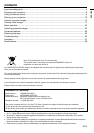
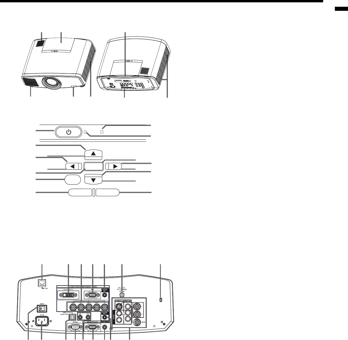
Overview
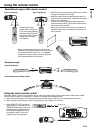
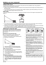
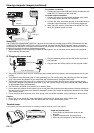
Control panel
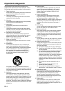
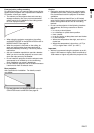
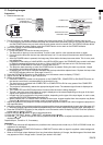
Terminal board
1 2 6
7 8
4 53
POWER
MENU
ENTER
STATUS
AUTO POSITION
COMPUTER
ZOOM/FOCUS LENS SHIFT
KEYSTONE
VIDEO
VOLUME
1
5
6
2
3
4
7
8
9
11
10
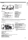
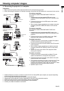
1 Speaker
2 Control panel (inside the cover)
3 Air outlet grille
4 Remote control sensor (Front)
5 Air inlet grille
6 Remote control sensor (Rear)
7 Terminal board
8 Air outlet grille
1 POWER button
2 AUTO POSITION /
button
3 COMPUTER /
button
4 KEYSTONE / ENTER button
5 MENU button
6 ZOOM / FOCUS button
7 LENS SHIFT button
8 VOLUME /
button
9 VIDEO /
button
10 POWER indicator
11 STATUS indicator
2 3 4 5 6 71
9 11 13 14 16128 10 15
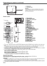
1 LAN terminal
• Used for projector control by computer.
2 COMPUTER / COMPONENT VIDEO DVI-D
(HDCP) terminal (DVI-D 24-pin)
3 COMPUTER / COMPONENT VIDEO IN-2 terminal
(R/PR, G/Y, B/PB, H/HV, V) (BNC)
4 COMPUTER / COMPONENT VIDEO IN-1 terminal
(Mini D-SUB 15-pin)
5 AUDIO IN-1 terminal (Mini jack)
6 Power terminal for wireless LAN unit (DC OUT
5V 1.5A MAX)
• Do not use the power terminal as a power for
other devices than the specifi ed wireless LAN unit.
(Wireless LAN unit isn’t packaged together with the
projector.)
Important:
• While the menu or the screen for the keystone, lens shift and zoom/focus adjustment, or password entry is being
displayed, the COMPUTER, VIDEO, AUTO POSITION and VOLUME buttons function as the
,
,
and
but-
tons respectively.
• While the menu is on the screen, the KEYSTONE button functions as the ENTER button.
7 Kensington Security Lock Standard connector
8 Main power switch
O : Off I : ON
9 Power jack
10 USB terminal
11 SERIAL terminal (D-SUB 9-pin)
• Used for projector control by computer. Contact your dealer for details.
12 REMOTE IN / OUT jack
13 MONITOR OUT terminal (Mini D-SUB 15-pin)
14 AUDIO OUT terminal (Mini jack)
15 AUDIO IN-2 terminal (Mini jack)
16 VIDEO IN and AUDIO IN terminals