


34
DISASSEMBLY INSTRUCTIONS
11
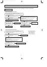
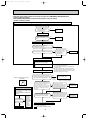
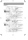
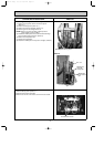
(1) Slide the sleeve and check if there is a locking lever or not.
(2) The terminal with this connector has the
locking mechanism.
1Slide the sleeve.
2Pull the terminal while
pushing the locking
lever.
1Hold the sleeve, and
pull out the terminal
slowly.
The terminal which has the locking mechanism can be detached as shown below.
There are two types ( Refer to (1) and (2)) of the terminal with locking mechanism.
The terminal without locking mechanism can be detached by pulling it out.
Check the shape of the terminal before detaching.
<"Terminal with locking mechanism" Detaching points>
Connector
Sleeve
Locking lever
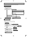
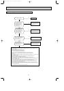
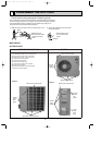
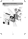
MUZ-GB50VA
OUTDOOR UNIT
OPERATING PROCEDURE PHOTOS
1. Removing the cabinet
(1) Remove the screws of the service panel.
(2) Remove the screws of the top panel.
(3) Remove the screw of the valve cover.
(4) Remove the service panel.
(5) Remove the top panel.
(6) Remove the valve cover.
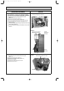
(7) Remove the screws of the cabinet.
(8) Remove the cabinet.
(9) Remove the screws of the back panel.
(10)
Remove the back panel.
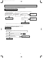
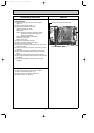
Photo 2
Photo 1
Photo 3
Screw of the top panel
Screws of the cabinet
Screws
of the
cabinet
Screws
of the
top
panel
Screw of the motor support
Set screws of the back panel
Screws
of the
cabinet
Screw of the service panel
Screw
of the
valve
cover
Screws
of the
back
panel
OB455 A--2qxp 06.7.31 2:50 PM Page 34