


8
7
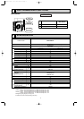
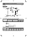
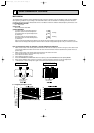
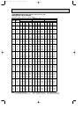
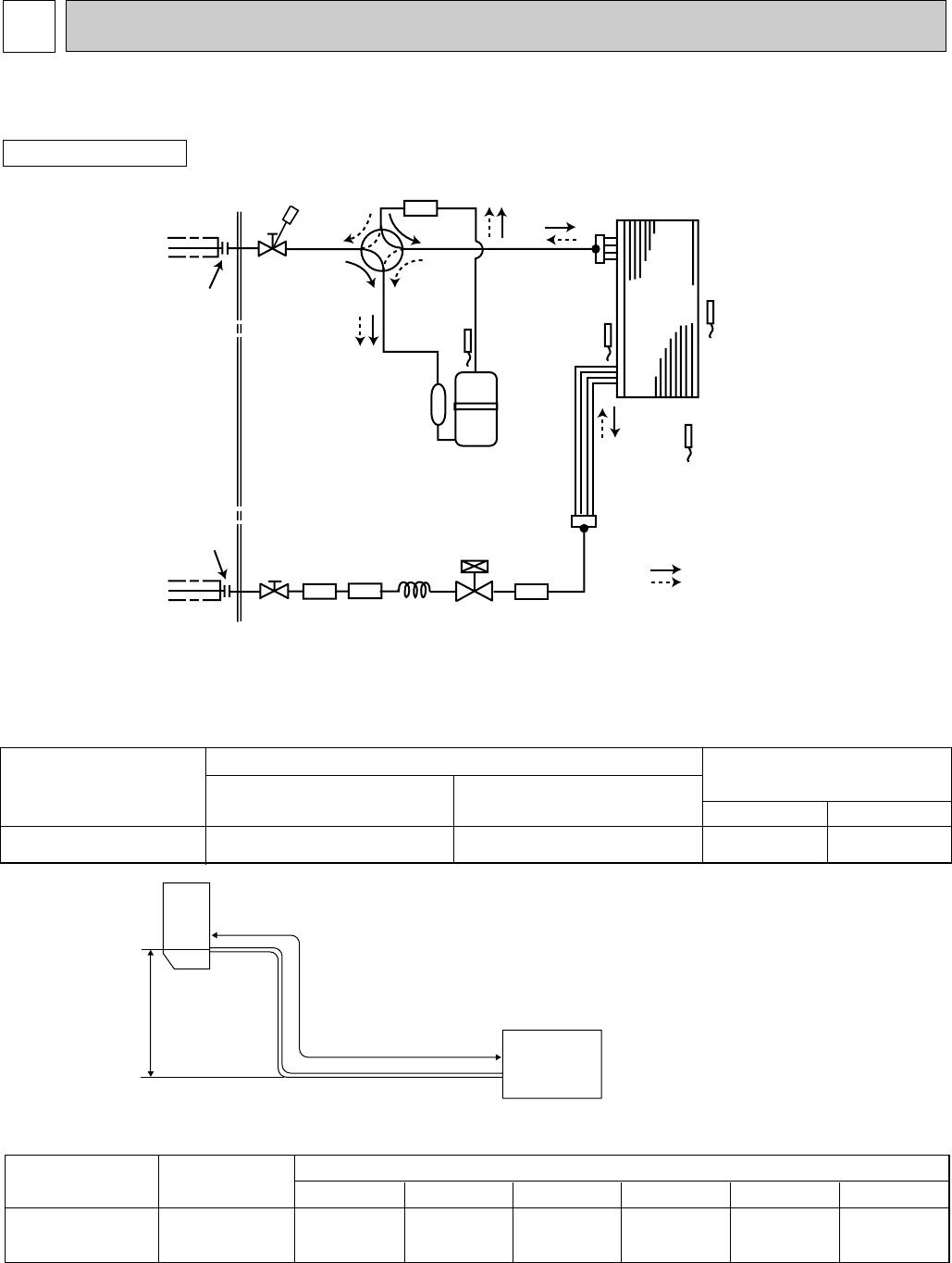
REFRIGERANT SYSTEM DIAGRAM
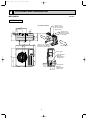
MUZ-GB50VA
OUTDOOR UNIT
Unit:mm
Outdoor
heat
exchanger
Flared connection
Defrost
thermistor
RT61
Discharge
temperature
thermistor
RT62
Flared connection
Stop valve
Stop valve
(with service port)
Capillary tube
[3.6✕[2.4✕50
Refrigerant flow in cooling
Compressor
4-way valve
Refrigerant flow in heating
Refrigerant pipe [12.7
(with heat insulator)
Refrigerant pipe [6.35
(with heat insulator)
LEV
R.V. coil
OFF
ON
Muffler
#100
Strainer
#100
Receiver
Outdoor heat
exchanger
temperature
thermistor
RT68
Ambient
temperature
thermistor
RT65
Strainer
#100
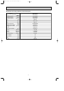
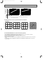
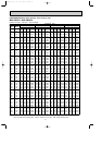
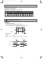
ADDITIONAL REFRIGERANT CHARGE (R410A:g)
Max. length
A
Max. Height
difference
B
Indoor
unit
Outdoor unit
MAX. REFRIGERANT PIPING LENGTH and MAX. HEIGHT DIFFERENCE
Max. length
A
30
Max. Height difference
B
15
Model
Gas
12.7
Liquid
6.35
Piping size O.D : mm
Refrigerant piping : m
MUZ-GB50VA
Model
MUZ-GB50VA
Refrigerant piping length (one way)
Outdoor unit
precharged
1,500
15m
160
20m
260
25m
360
30m
460
7m
0
10m
60
Calculation : Xg=20g/m ✕ (Refrigerant piping length (m)–7)
NOTE : Refrigerant piping exceeding 7m requires additional refrigerant charge according to the calculation.
OB455A--1qxq 06.7.31 2:19 PM Page 8