


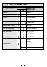
20
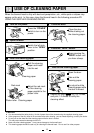
13
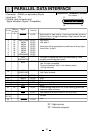
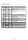
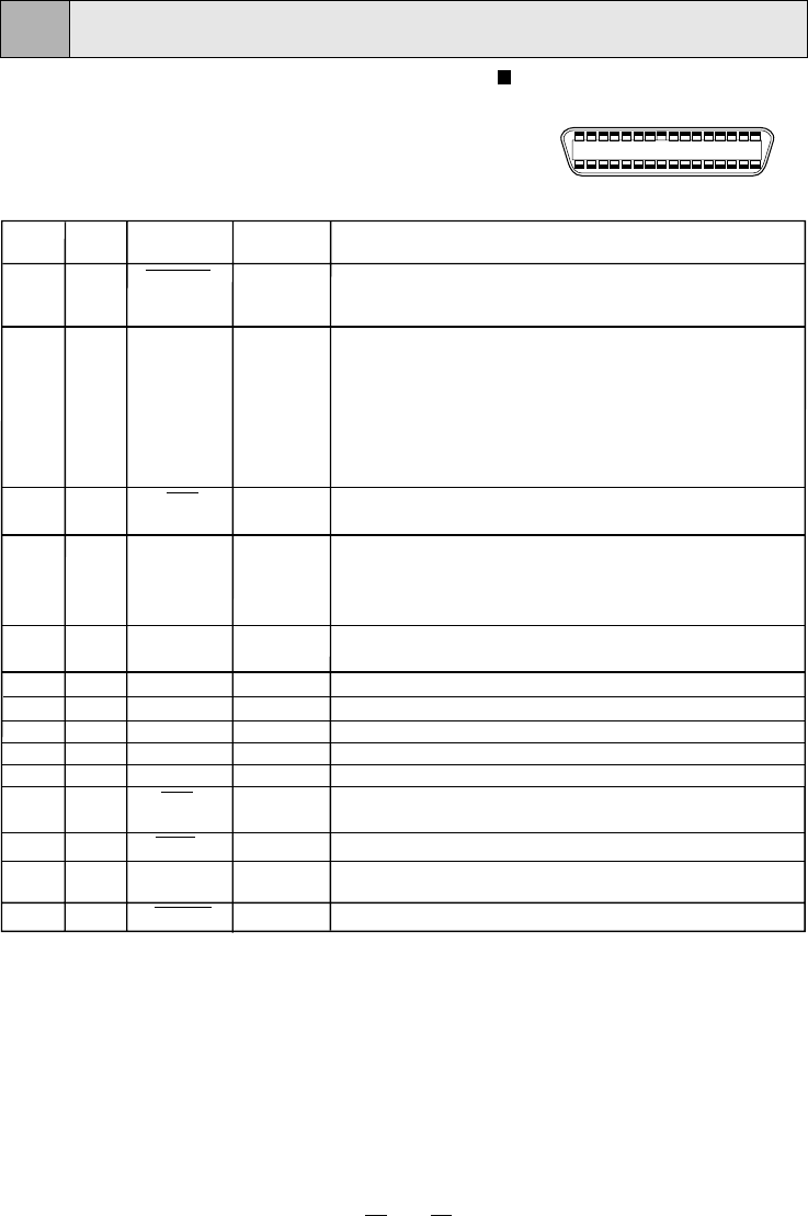
• Connector JD36SL or equivalent (36 pin)
• Input level TTL
• Parallel input connector port
Signal allocation (Signal : Compatible)
PARALLEL DATA INTERFACE
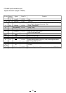
Pin No.
Return
pin No.
Signal
From/To
Function
119
STROBE PC/DP
Strobe pulse for data reading. Incoming pulse width shoud be
0.5µs minimum. At regular conditions, “High” data will be read
after becoming “Low”.
High: data 1
Low: data 0
Information will be expressed for parallel data of every signal
from bit No.1 to No.8.
The signal is yielded after data input has ended by a data
reception acknowledgement pulse.
High: DP data is not accepted.
Low: DP data is accepted.
The signal becomes “High” in the following cases:
• During data entry
High: No paper
Low: Paper available
High
High
Earth
PeripheralLogicHigh
Clears sending data to this unit. (Low) Incoming pulse width
should be 100µs minimum.
Low: Abnormal condition occurs in DP. (e.g. error)
Unused
Low
PC/DP
PC/DP
PC/DP
PC/DP
PC/DP
PC/DP
PC/DP
PC/DP
PC/DP
PC/DP
PC/DP
PC/DP
PC/DP
PC/DP
PC/DP
PC/DP
PC/DP
PC/DP
2
3
4
5
6
7
8
9
20
21
22
23
24
25
26
27
DATA1(LSB)
DATA2
DATA3
DATA4
DATA5
DATA6
DATA7
DATA8(MSB)
10
28
ACK
(ACKNOWLEDGE)
11
29
BUSY
12
P•E
(PAPAER END)
13
14
16•17
18
Earth
19 - 30
31
32
15•
33 - 35
36
SELECT
AutoFd
GND
High
INIT
GND
Fault
NC
SelectIn
16
PARALLEL TERMINAL SIGNAL
Pin number
18
1
36 19
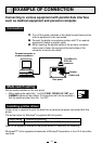
DP : Digital printer
PC : Personal computer