


11
2 - inlet
1 - inlet
2 - inlet
1 - inlet
2 - inlet
1 - inlet
-200(-80)
-150(-60)
-100(-40)
-50(-20)
0
50(20)
012
50 100 150 200
[CFM]
345
6
[CMM]
2 - inlet
1 - inlet
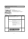
Air flow rate
Static pressure [Pa(in.W.G.%10
-2
)]
-200(-80)
-150(-60)
-100(-40)
-50(-20)
0
50(20)
012
50 100 150 200
[CFM]
345
6
[CMM]
Static pressure [Pa(in.W.G.%10
-2
)]
-200(-80)
-150(-60)
-100(-40)
-50(-20)
0
50(20)
012
50 100 150 200
[CFM]
3456
[CMM]
Air flow rate
Static pressure [Pa(in.W.G.%10
-2
)]
-200(-80)
-150(-60)
-100(-40)
-50(-20)
0
50(20)
02
50 100 150 200 250
[CFM]
48
[CMM]
6
Air flow rate
Static pressure [Pa(in.W.G.%10
-2
)]
-200(-80)
-150(-60)
-100(-40)
-50(-20)
0 0
50(20)
02
50 100 150 200 250
[CFM]
48
[CMM]
6
Air flow rate
Static pressure [Pa(in.W.G.%10
-2
)]
-200(-80)
-150(-60)
-100(-40)
-50(-20)
50(20)
02
50 100 150 200 250
[CFM]
48
[CMM]
6
Air flow rate
Static pressure [Pa(in.W.G.%10
-2
)]
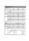
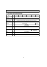
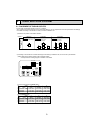
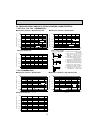
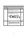
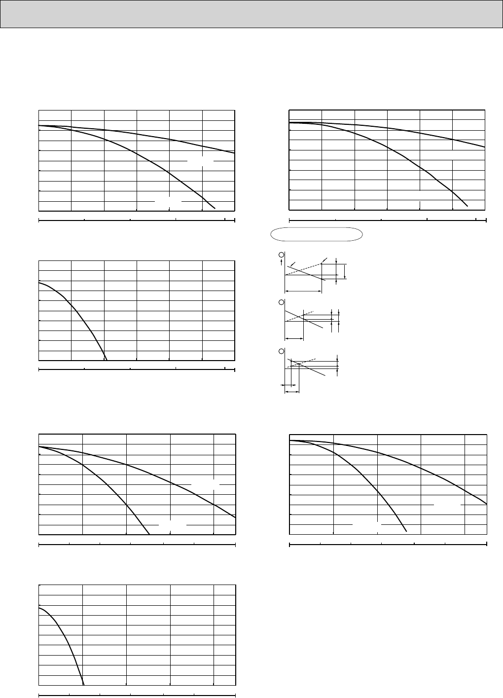
2 PLFY-P36NBMU-E(R1)
Multifunction casement + Standard filter Multifunction casement + High efficiency filter
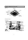
Taking air into the unit
Taking air into the unit
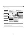
5-4. FRESH AIR INTAKE AMOUNT & STATIC PRESSURE CHARACTERISTICS
1 PLFY-P12 · P18 · P24 · P30NBMU-E(R1)
Multifunction casement + High efficiency filter Multifunction casement + Standard filter
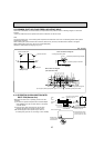
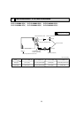
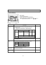
Q
0
B
A
C
1
Curve in the
graphs.
Duct characteristics
at site
Q
A
EC
2
Q
Qa
AD
3
Q
…
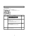
Designed amount of fresh air intake
<CMM (CFM)>
A
…
Static pressure loss of fresh air
intake duct system with air flow
amount Q <Pa (in.W.G.o10
-2
)>
B
…
Forced static pressure at air condi-
tioner inlet with air flow amount Q
<Pa (in.W.G.o10
-2
)>
C
…
Static pressure of booster fan with air
flow amount Q <Pa (in.W.G.o10
-2
)>
D
…
Static pressure loss increase amount
of fresh air intake duct system for air
flow amount Q <Pa (in.W.G.o10
-2
)>
E
…
Static pressure of indoor unit with air
flow amount Q <Pa (in.W.G.o10
-2
)>
Qa
…
Estimated amount of fresh air
intake without D <CMM (CFM)>
How to read curves