25
Notes
· High voltage is applied to the connecter (CNMF) for the fan motor. Pay attention to the service.
· Do not pull out the connector (CNMF) for the motor with the power supply on.
(It causes trouble of the indoor controller board and fan motor)
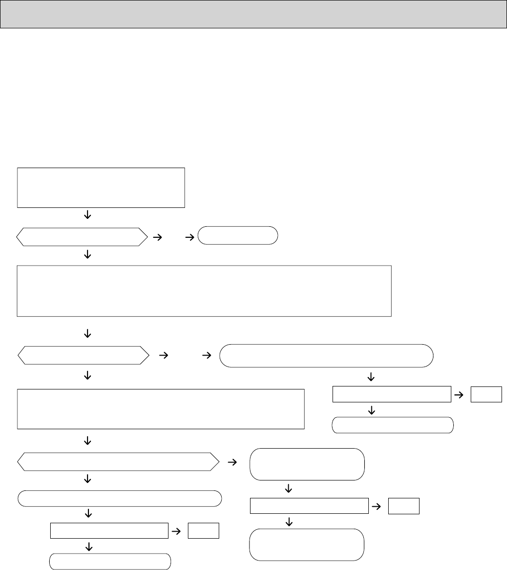
Self check
Conditions : The indoor fan cannot turn around.
No
Wiring contact check
Contact of fan motor connector (CNMF)
Contact of power supply cable
Fan motor position sensor signal check
Turn around the fan motor more than one revolution slowly, and check
the voltage TEST POINT V
FG (between 7(+) and 4(-)).
Check method of indoor fan motor (fan motor/indoor controller board)
Wiring recovery
Trouble of the indoor controller board
Replace the indoor controller board.
Trouble of the fan motor
Replace the fan motor.
Does the voltage repeat DC0V and DC15V?
Replace the indoor controller board.
Is the voltage normal?
Is there contact failure ?
Yes
No
Yes
No
Yes
Power supply check (Remove the connector (CNMF))
Measure the voltage in the indoor controller circuit
board.
TEST POINT
: VDC (between 1 (+) and 4 (-) of the fan connector): VDC DC294~325V
TEST POINT : VCC (between 5 (+) and 4 (-) of the fan connector): VCC DC15V
Yes
Check the operation of fan.
OK
END
Replace the fan motor.
NG
Check the operation of fan.
OK
END
Replace the fan motor.
NG
Yes
Check the operation of fan.
OK
END
Replace the indoor
controller board
NG
10-1-3. DC Fan motor (fan motor/indoor controller board)


