


14
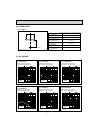
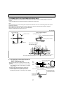
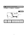
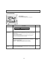
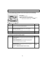
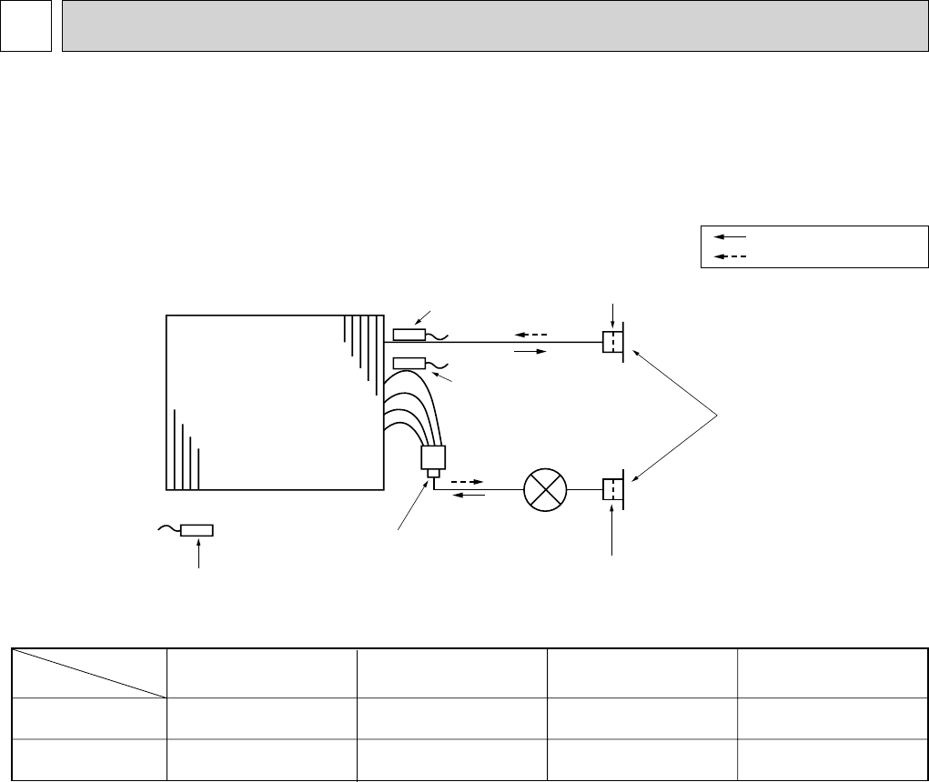
8 REFRIGERANT SYSTEM DIAGRAM
Refrigerant flow in cooling
Refrigerant flow in heating
Strainer (#100mesh)
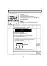
Strainer (#100mesh)
Strainer1 (#50mesh)
Strainer2 (#100mesh)
Heat exchanger
Room temparature thermistor TH21
Gas pipe thermistor TH23
Liquid pipe thermistor TH22
Linear expansion valve
Gas pipe
Liquid pipe
Flare connection
Gas pipe
Liquid pipe
PLFY-P12/P15NBMU-E
PLFY-P12/P15NBMU-ER1
:12.7 (1/2'')
:6.35 (1/4'')
PLFY-P18NBMU-E
PLFY-P18NBMU-ER1
:12.7 (1/2'')/:15.88 (5/8'')
:6.35 (1/4'')/:9.52 (3/8'')
PLFY-P24/P30NBMU-E
PLFY-P24/P30NBMU-ER1
:15.88 (5/8'')
:9.52 (3/8'')
PLFY-P36NBMU-E
PLFY-P36NBMU-ER1
:15.88 (5/8'')/:19.05 (3/4'')
:9.52 (3/8'')
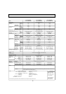
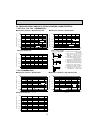
Item
Model
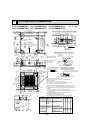
Unit : mm (inch)
PLFY-P12NBMU-E(R1) PLFY-P15NBMU-E(R1) PLFY-P18NBMU-E(R1)
PLFY-P24NBMU-E(R1) PLFY-P30NBMU-E(R1) PLFY-P36NBMU-E(R1)