


Hardware Installation
CA-132/132I User’s Manual
2-5
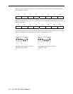
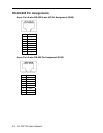
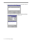
At this point, the start of I/O addresses of Port 2 will be automatically configured at 188.
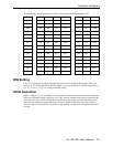
A3 A4 A5 A6 A7 A8 A9
8 1 2 4 8 1 2 Hex
On On On On On On On
0×000
On On On On On On Off
0×200
On On On On On Off Off
0×300
On On On On Off Off Off
0×380
On On On Off Off Off Off
0×3C0
On On Off Off Off Off Off
0×3E0
On Off Off Off Off Off On
0×3F0
Off Off Off Off Off Off Off
0×3F8
Off On On On On On On
0×008
Off Off On On On On On
0×018
Off Off Off On On On On
0×038
Off Off Off Off On On On
0×078
Off Off Off Off Off On On
0×0F8
Off
Off Off Off Off
Off On
0×2F8
IRQ Setting
CA-132/132I Series has a jumper selectable function for you to configure IRQ settings. Before you
insert a CA-132/132I board into the PC/104 interface, you need to choose an available jumper from 3,
4, 5, 6, 7, 9, 10, 11, 12, or 15 to configure the IRQ setting.
Initial Inspection
Before we ship CA-132/132I products, we first perform a careful mechanical and electrical inspection
of these serial boards. Products should be free of any marks or scratches and in perfect electrical order
when customers receive them. Handle these boards only by their edges, since the static charge from
your body may damage the integrated circuits. Always keep the boards in their anti-static package
whenever they are not installed. You can also use this package to return the board should it need to be
repaired.