EDS-408A/405A Series User’s Manual Featured Functions
3-21
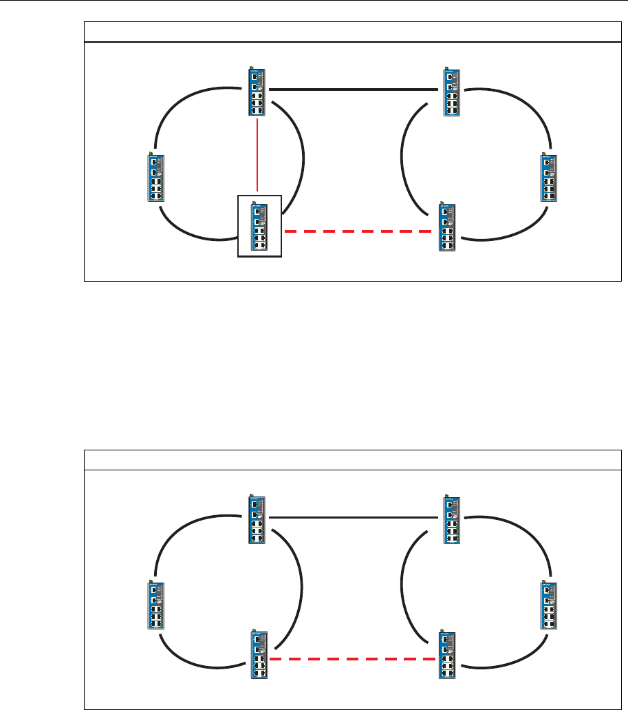
Ring Coupling for a “Turbo Ring” Ring
Switch A: "Coupler"
Switch B
Switch D
Coupling Port
Switch C
Main Path
Coupling Port
Backup Path
Coupling
Control Port
To configure the Ring Coupling function for a “Turbo Ring” ring, select two EDS units (e.g.,
Switch A and B in the above figure) in the ring, and another two EDS units in the adjacent ring
(e.g., Switch C and D).
Decide which two ports in each switch are appropriate to be used as coupling ports, and then link
them together. Next, assign one switch (e.g., Switch A) to be the “coupler,” and connect the
coupler’s coupling control port with Switch B (for this example).
The coupler switch (i.e., Switch A) will monitor switch B through the coupling control port to
determine whether or not the coupling port’s backup path should be recovered.
Ring Coupling for a “Turbo Ring V2” Ring
Switch A
Switch B
Switch D
Coupling Port (Primary)
Switch C
Main Path
Coupling Port (Backup)
Backup Path
Note that the ring coupling settings for a “Turbo Ring V2” ring are different from a “Turbo Ring”
ring. For Turbo Ring V2, Ring Coupling is enabled by configuring the “Coupling Port (Primary)”
on Switch B, and the “Coupling Port (Backup)” on Switch A only. You do not need to set up a
coupling control port, so that a “Turbo Ring V2” ring does not use a coupling control line.
The “Coupling Port (Backup)” on Switch A is used for the backup path, and connects directly to
an extra network port on Switch C. The “Coupling Port (Primary)” on Switch B monitors the
status of the main path, and connects directly to an extra network port on Switch D. With ring
coupling established, Switch A can activate the backup path as soon as it detects a problem with
the main path.


