


NPort 5400 Series User’s Manual Getting Started
2-4
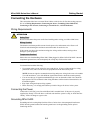
ATTENTION
This product is intended to be mounted to a well-grounded mounting surface such as a metal
panel.
SG: The Shielded Ground (sometimes called Protected Ground)
contact is the left most contact of the 3-pin power terminal
block connector when viewed from the angle shown here.
Connect the SG wire to an appropriate grounded metal
surface.
Connecting to the Network
Connect one end of the Ethernet cable to NPort 5400’s 10/100M Ethernet port and the other end of
the cable to the Ethernet network. If the cable is properly connected, NPort 5400 will indicate a
valid connection to the Ethernet in the following ways:
y The Ethernet LED maintains a solid green color when connected to a 100 Mbps Ethernet
network.
y The Ethernet LED maintains a solid yellow color when connected to a 10 Mbps Ethernet
network.
y The Ethernet LED will flash when Ethernet packets are being transmitted or received.
Connecting to a Serial Device
Connect the serial data cable between NPort 5400 and the serial device.
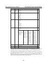
LED Indicators
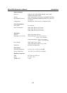
The top panels of NPort 5400 have four LED indicators, as described in the following table.
LED Name LED Color LED Function
red
Steady on: Power is on and NPort is booting up.
Blinking: Indicates an IP conflict, or DHCP or BOOTP server did
not respond properly.
green
Steady on: Power is on and NPort is functioning normally.
Blinking: The NPort has been located by NPort Administrator’s
Location function
Ready
off Power is off, or power error condition exists.
orange 10 Mbps Ethernet connection.
green 100 Mbps Ethernet connection.
Ethernet
off
Ethernet cable is disconnected, or has a short.
orange Serial port is receiving data.
green Serial port is transmitting data.
P1, P2,
P3, P4
off No data is being transmitted or received through the serial port.