


10 FFD 2.5" and 3.5" IDE Plus Flash Disk User Manual 48-SR-003-03-7L Rev 2.1
5.3 Interface Connectors
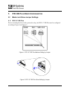
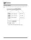
5.3.1 FFD 2.5” IDE Plus
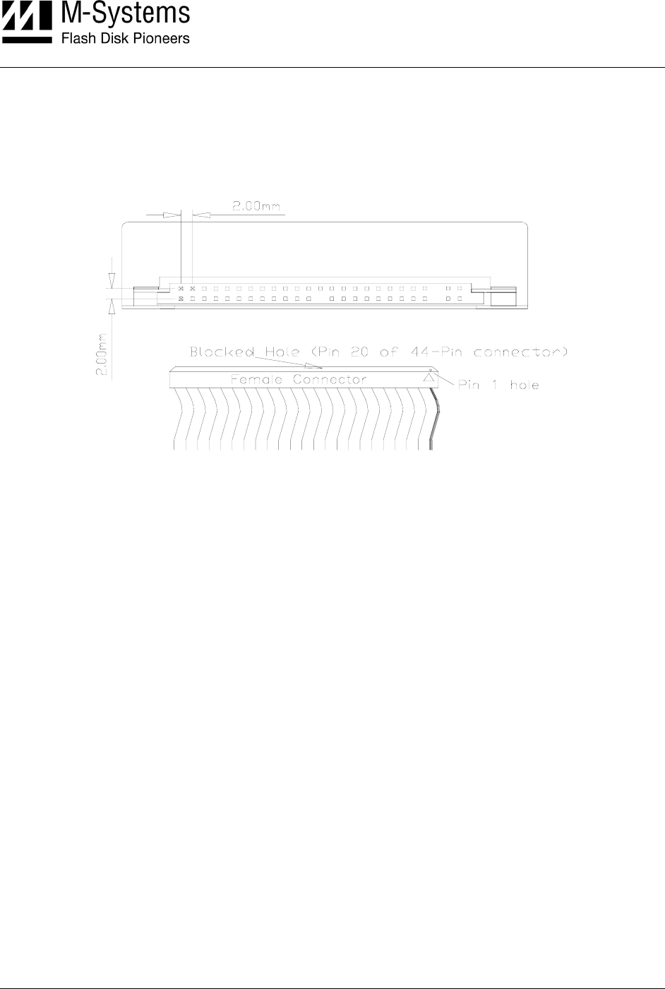
The FFD 2.5” IDE Plus has a 2.00 mm pitch interface connector located on the rear panel. The
DC power and IDE bus are input through a non-shielded 50-pin flat cable.
Figure 6: FFD 2.5” IDE Plus Interface Connector
It is recommended that the mating connector be blocked at pin 27 using a special plastic key (the
key can be ordered from the connector manufacturer). This prevents possible damage to the disk
by connecting the cable with a 180º rotation.
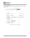
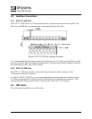
5.3.2 FFD 3.5” IDE Plus
The FFD 3.5” IDE Plus should be connected using a 40-pin I/O cable connector with a
2.54 mm pitch interface connector.
As with the FFD 2.5” IDE Plus, it is recommended that the mating connector be blocked at pin
27 using a special plastic key (the key can be ordered from the connector manufacturer). This
prevents possible damage to the disk by connecting the cable with a 180º rotation.
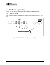
5.4 IDE Cable
The cable length should not exceed 18 inches.