PRI Card User Guide
4 CommPlete Communications Server
Card Components
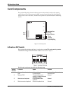
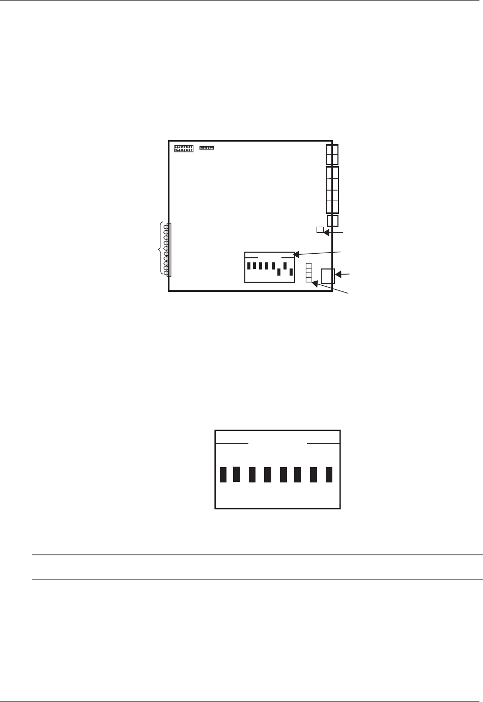
The 8-position DIP switch is located on the lower portion of the card and is used to set the operating
modes of the card. The T1 line connector is a RJ48C connector located on lower back of the card and is
used to connect to the T1 line facility. The PRI card components are descirbed in detail in the following
sections.
J101
J103
J100
J1
LED 1
LED 2
LED 3
LED 4
LED 5
LED 6
LED 7
LED 8
LED 9
LED 10
J9
J8
1 2 3 4 5 6 7 8
OPEN
F5
F1
F2
F3
F4
Power Supply Fuse
F5 (3 Amp)
T1 Line
Connector
T1 Line Protection
Fuses F1-F4 (3 Amp)
8-Position DIP Switch
Status
LEDs
Figure 2. Card Components
8-Position DIP Switch
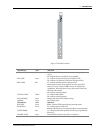
The 8-position DIP switch shown in Figure 4 is used to select various PRI card operating modes.
The default settings of the DIP switch mod
ule are also shown in Figure 3.
OPEN
1 2 3 4 5 6 7 8
Figure 3. 8-position DIP Switch
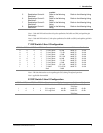
The DIP-switch selections are described in the following listings.
Switch
Number
Function Open Closed
1
Selects Jitter Attentuation
path
Activate Jitter Attentuation
in receive path
Activate Jitter Attentuation in
transmit path
2 Selects TOS Transmit data inputs
ignored, instead transmits
a stream of ones
Normal
3 Selects local loopback Local loopback test
enabled
Normal
4 Selects remote loopback Remote loopback test Normal


