


Chapter 12 – V.24 and V.25 Commands
Multi-Tech Systems, Inc. Wireless GSM/GPRS AT Commands (Document Number S000293I) 101
DTE-DCE Local Flow Control +IFC
Description: This command is controls the operation of local flow control between the DTE and DCE.
Values: < DCE_by_DTE >
0 none (supported)
1 Xon/Xoff local circuit 103 (not supported)
2 RTS (supported)
3 Xon/Xoff global on circuit 103 (not supported)
Important Note: When this parameter is set to 2 (DTE invokes flow control through RTS) DCE
behaviour is as follows:
• If the DCE has never detected RTS in the high (or ON) condition since startup then it ignores
RTS as it assumes that this signal is not connected.
• As soon as the DCE detects RTS high the signal acts on it. Therefore subsequent RTS
transition to OFF will prevent the DCE from sending any further data in both online and
offline modes.
• This behavior allows the user to use the default settings (hardware flow control) and leave
RTS disconnected. In the case where RTS is connected and is high at least once, it acts on
the DCE.
< DTE_by_DCE >
0 none (supported)
1 Xon/Xoff circuit 104 (not supported)
2 CTS (supported)
Note: When this parameter is set to 0 (none), then CTS is kept high all the time.
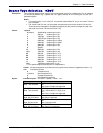
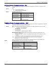
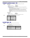
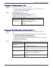
Syntax: Command syntax: AT+IFC=<DCE_by_DTE>,<DTE_by_DCE>
Command Possible responses
AT+IFC?
+IFC: 2,2
OK
Note: Current values
AT+IFC=?
+IFC: (0,2),(0,2)
OK
Note: Possible values
AT+IFC=0,0 OK
Note: New values
Set DCD Signal &C
Description: This commands controls the Data Carrier Detect (DCD) signal.
Values: <n>
0 DCD always on
1 DCD matches the state of the remote modem’s data carrier
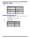
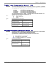
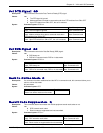
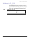
Syntax: Command syntax: AT&C <n>
Command Possible responses
AT&C0
Note: DCD always on
OK
Note: Command valid
AT&C1
Note: DCD matches state of the remote
modem’s data carrier
OK
Note: Command valid