


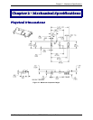

Chapter 2 – Mechanical Specifications
Multi-Tech Systems, Inc. SocketModem MT5600SMI Developer’s Guide 10
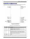
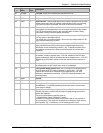
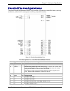
Pin
#
Signal
Name
I/O
Type
Description
31 DTRIND
DTR LED. Output from 74AC05 with 1500 Ohms pull-up.
32 TXIND
TX LED. Output from 74AC05 with 1500 Ohms pull-up.
33 –RTS I
Request to Send. RTS signal is used for hardware flow control.
34 –RXD O
Received Data. Used to send data received from the telephone line and also
modem responses to the DTE. Modem response take priority over incoming
data. When no data is transmitted, the signal is held in mark condition.
35 –TXD I
Transmit Data. The DTE uses this line to send data to the modem for
transmission over the telephone line or to transmit commands to the modem.
The DTE should hold this circuit in the mark state when no data is being
transmitted or during intervals between characters.
36 –RI O
Ring Indicate. –RI output ON (low) indicates the presence of an ON segment
of a ring signal on the telephone line.
The modem will not go off-hook when –RI is active; the modem waits for –RI
to go inactive before going off-hook.
37 –DSR O
Data Set Ready. –DSR indicates modem status to the DTE. –DSR OFF
(high) indicates that the DTE is to disregard all signals appearing on the
interchange circuits except Ring Indicator (–RI). It reflects the status of the
local data set, and does not indicate an actual link with any remote data
equipment.
38 –CTS O
Clear To Send. –CTS is controlled by the modem to indicate whether or not
the modem is ready to transmit data. –CTS ON, indicates to the DTE that
signals presented on TXD will be transmitted to the telephone line. –CTS OFF
indicates to the DTE that it should not transfer data across the interface on
TXD.
39 –DCD O
Data Carrier Detect. –DCD output is ON (low) when a carrier is detected on
the telephone line or OFF (high) when carrier is not detected.
40 –DTR I
Data Terminal Ready (Active Low). The –DTR input is turned ON (low) by
the DTE when the DTE is ready to transmit or receive data. –DTR ON
prepares the modem to be connected to the telephone line, and, once
connected, maintains the connection. –DTR OFF places the modem in the
disconnect state.
41 DGND
Ground.
61 VCC
3.3V DC Power.
63 AGND
Analog Ground. Analog ground is tied common with DGND on the
SocketModem. To minimize potential ground noise issues, connect audio
circuit return to AGND.
64 SPKR
Speaker Output. SPKR is a single ended-output. SPKR is tied directly to the
CODEC. One side of a differential AC output coupled through a 6.8K ohm
resistor and capacitor.
The call progress speaker interface signal is:
· Digital speaker output (DSPKOUT); output
DSPKOUT is a square wave output in data mode used for call progress or
carrier monitoring. This output can be optionally connected to a low-cost on-
board speaker, e.g., a sounducer, or to an analog speaker circuit.