Index MultiVOIP User Guide
422
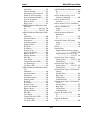
DTMF frequency chart ................. 197
DTMF Gain (High Tones) field
analog........................................ 181
T1/E1 ........................................ 106
DTMF Gain (Low Tones) field
analog........................................ 181
T1/E1 ........................................ 106
DTMF Gain field
analog........................................ 181
T1/E1 ........................................ 106
DTMF In/Out of Band field
analog........................................ 182
T1/E1 ........................................ 107
DTMF inband
analog........................................ 182
T1/E1 ........................................ 107
DTMF out of band
analog........................................ 182
T1/E1 ........................................ 107
DTMF Parameters
T1/E1 ........................................ 106
DTMF, custom tone pairs
analog................................ 207, 208
T1/E1 ................................ 133, 134
Duration (call progress) field........ 327
Duration (DTMF) field
analog........................................ 182
T1/E1 ........................................ 107
Duration (SMTP logs) field
analog........................................ 213
T1/E1 ........................................ 139
Duration (statistics, logs) field......332
Dynamic Jitter Buffer field
analog........................................ 185
T1/E1 ........................................ 110
Dynamic Jitter field group
analog........................................ 185
T1/E1 ........................................ 110
Dynamic Jitter fields
analog........................................ 186
T1/E1 ........................................ 111
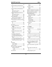
E
E&M interface (MVP210)
matching telco trunk line ............73
uses of......................................... 73
E&M interface (MVP-410/810)
matching telco trunk line ............71
uses of .........................................71
E&M Interface Parameter fields
Interface ....................................199
Pass Through.............................199
Signal ........................................199
Type ..........................................199
Wink Timer...............................199
E&M Parameter definitions ..........199
E&M Parameters...........................198
E1 Parameter definitions121, 122, 124
Clocking....................................124
Line Build-Out..........................124
Line Coding...............................124
PCM Law..................................124
Pulse Shape Level.....................124
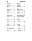
E1 Parameter fields
CAS Protocol ........................122
CRC Check ...............................122
Frame Format............................122
Long-Haul Mode.......................122
E1 Parameters screen ....................120
E1 Statistics field definitions344, 345,
346
E1 Statistics fields
Bipolar Variation.......................346
Blue Alarm................................344
Excessive Zeroes.......................346
Loss of Frame Alignment..........344
Loss of MultiFrame Alignment.345
Receive Slip ..............................346
Receive Timeslot 16 Alarm
Indication Signal ...................345
Receive Timeslot 16 Loss of
MultiFrame Alignment..........346
Receive Timeslot 16 Loss of Signal
..............................................345
Red Alarm.................................344
Status Freeze Signalling Active 345
Transmit Data Overflow............345
Transmit Data Underrun ...........346
Transmit Line Open ..................346
Transmit Line Short ..................345
Transmit Slip.............................346
Transmit Slip Negative .............346
Transmit Slip Positive...............345
Yellow Alarm............................345
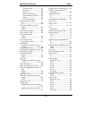
E1 telephony parameters.................91
E1/ISDN Parameter definitions.....123


