


MultiVOIP User Guide Mechanical Installation & Cabling
71
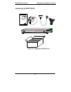
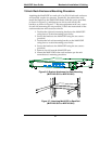
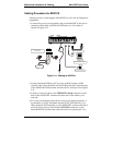
3. Connect a network cable to the ETHERNET 10BASET connector on
the back of the MultiVOIP. Connect the other end of the cable to your
network.
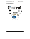
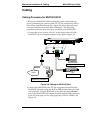
4. If you are connecting a station device such as an analog telephone, a
fax machine, or a Key Telephone System (KTS) (FXS interface), or a
PBX extension (FXO interface) to your MultiVOIP, connect one end of
an RJ-11 phone cord to the Channel 1 FXS/FXO connector on the back
of the MultiVOIP and the other end to the device or phone jack. You
will define the interface in the Interface dialog box in the software
when you configure the unit.
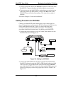
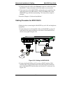
If you are connecting an E&M trunk from a telephone switch to your
MultiVOIP, connect one end of an RJ-45 phone cord to the Channel 1
E&M connector on the back of the MultiVOIP and the other end to
the trunk. Verify that the E&M Type in the E&M Options group of
the Interface dialog box is the same as the E&M trunk type support
by the telephone switch. See Appendix B for an E&M cabling pinout.
5.Repeat the above step to connect the remaining telephone equipment
to each Channel on your MultiVOIP.
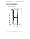
6.Ensure that the unit is properly connected to earth ground by
verifying that it is reliably grounded when mounted within a rack.
This can be accomplished by connecting a grounding wire between
the chassis and a metallic object that will provide an electrical
ground.
7.Turn on power to the MultiVOIP by placing the ON/OFF switch on
the back panel to the ON position. Wait for the Boot LED on the
MultiVOIP to go off before proceeding. This may take a few minutes.
Proceed to Chapter 4 to load the MultiVOIP software.