MultiVOIP User Guide Technical Configuration (Digital)
119
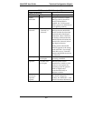
T1 Parameter Definitions (cont’d)
Field Name Values Description
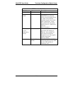
Line Build Out 0 dB, -7.5 dB,
-15 dB, -22.5 dB
To reduce the crosstalk on
received signals, a transmit
attenuator can be placed in the
data path. Transmit attenuation
is selectable. Default: O dB
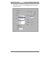
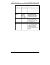
Pulse Shape
Level
0 to 40 Meters
40 to 81 m
81 to 122 m
122 to 162 m
162 to 200 m
Refers to length of cable
between MultiVOIP and
PBX/telco in meters. Most
common will be 0 to 40m.
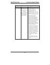
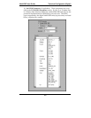
Clocking External/Internal
Set opposite to telco/PBX
setting. Example: if telco
clocking internal, set VOIP
clocking as external.
Line Coding AMI / B8ZS Match to PBX or telco.
PCM Law A-Law/Mu-Law Match to PBX or telco. “
Mu-law” is analog-to-digital
compression/expansion
standard used in North
America. “A-law” is European
standard.
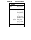
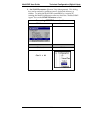
Yellow Alarm
Format
Bit 2 / 1111… Depending on the Frame
Format used, there are choices
of Yellow Alarm format, as
follows:
D4: -Bit2 = 0 in every speech
channel
-FS bit of frame 12 is forced
to one.
ESF: -Bit2 = 0 in every speech
channel
–1111111100000000 pattern
in data link channel.
Check with your PBX/telco
administrator for the correct
setting or use the default value
(1111 … ).


