


© National Instruments Corporation 2-1 SCXI Chassis User Manual
2
Configuring and Installing
the SCXI Chassis
This chapter contains instructions for configuring and installing the SCXI
chassis. It describes the following:
• Chassis address selection
• Voltage and fuse selection
• Chassis, modules, and accessories installation
• Fan filter maintenance
Chassis Description
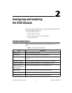
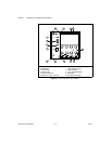
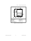
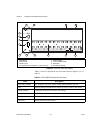
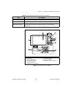
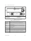
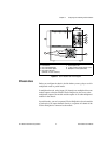
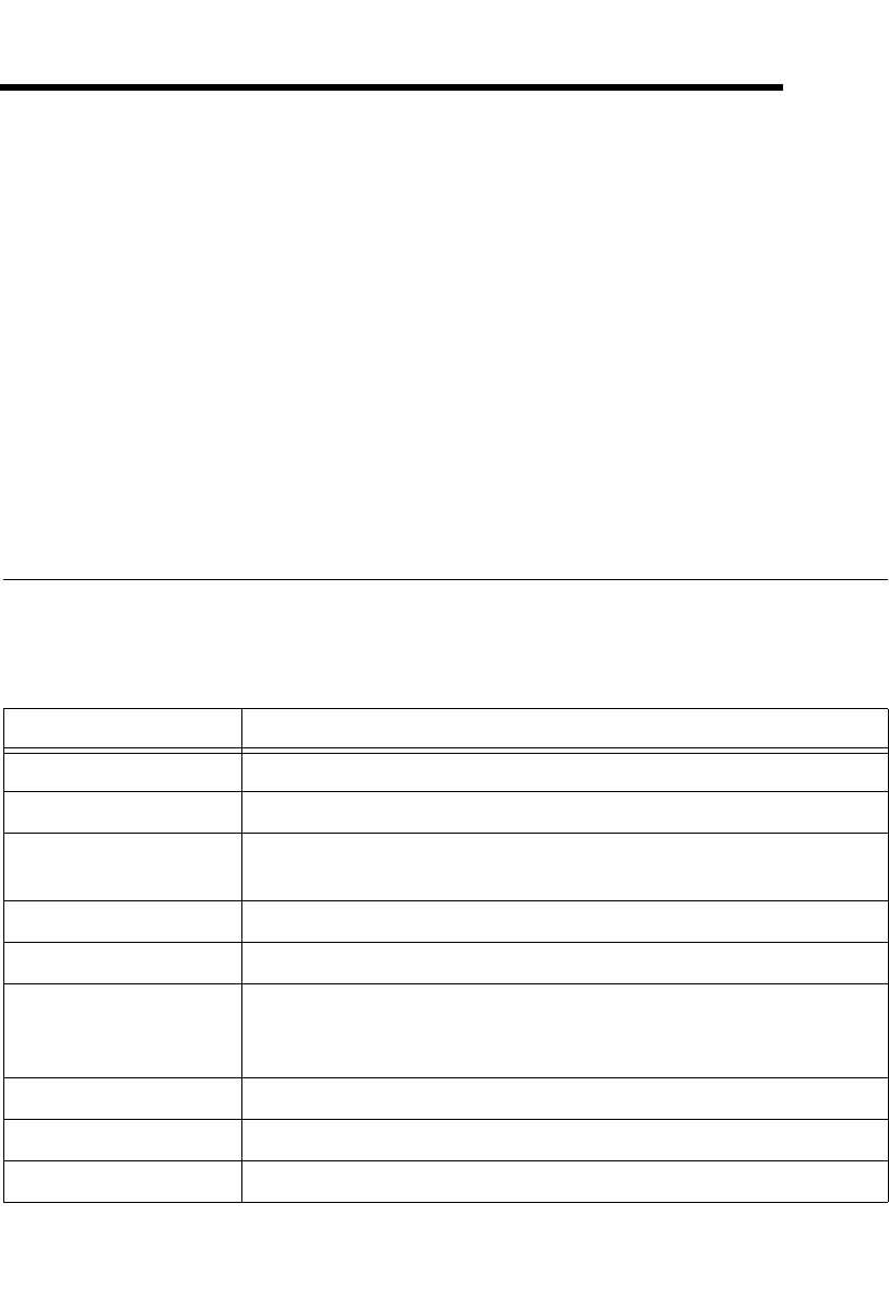
Table 2-1 describes the front view items shown in Figures 2-1, 2-2,
and 2-3.
Table 2-1. SCXI Chassis Front View Items
Item Definition
Power switch Powers the chassis on and off
Indicator light When lit, indicates that the chassis is powered on
Reset button Reinitializes Slot 0 and all modules to their power-on state when
pressed
Slot 0/power supply Contains the power supply and control circuitry for the chassis
Address DIP switches Determine the chassis address—SCXI-1000 and SCXI-1001
Address selection
jumpers (located behind
the front panel)
Determine the chassis address—SCXI-1000DC only
Module guides Guide modules to connect with the SCXIbus connector
Backplane Brings power, control lines, and analog bus connections to modules
Front threaded strips Secure modules in the chassis and attach front panels