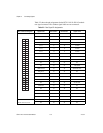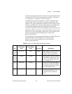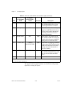
Chapter 2 Connecting Signals
SCXI-1141/1142/1143 User Manual 2-4 ni.com
analog ground. The inputs are protected against maximum input voltages
of up to ±15 V powered off and ±30 V powered on.
Caution Exceeding the differential or common-mode input voltage limits distorts input
signals. Exceeding the maximum common-mode input voltage rating can damage the
SCXI-1141/1142/1143 module, the SCXIbus, and the DAQ device. NI is not liable for any
damage resulting from such signal connections.
All eight channels have fully differential inputs, so you can
ground-reference the signals you measure. If the signals connected to the
differential amplified inputs are not ground referenced, connect a 100 kΩ
resistor from the negative input to ground to provide a DC path for the input
bias currents. If you do not do this, the bias currents of the instrumentation
amplifiers of the nonreferenced channels charge up stray capacitances,
resulting in uncontrollable drift and possible saturation.
Note The recommended SCXI-1304 or SCXI-1305 terminal block has all necessary
circuitry for AC or DC coupling and for floating or ground-referenced signals. The
SCXI-1304 AC/DC Coupling Terminal Block Installation Guide and SCXI-1305 AC/DC
Coupling BNC Terminal Block Installation Guide have instructions for signal connection.
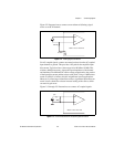
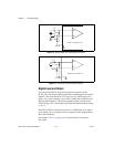
Figures 2-2 through 2-5 provide supplemental information on connecting signals to the
SCXI-1141/1142/1143 module.
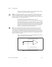
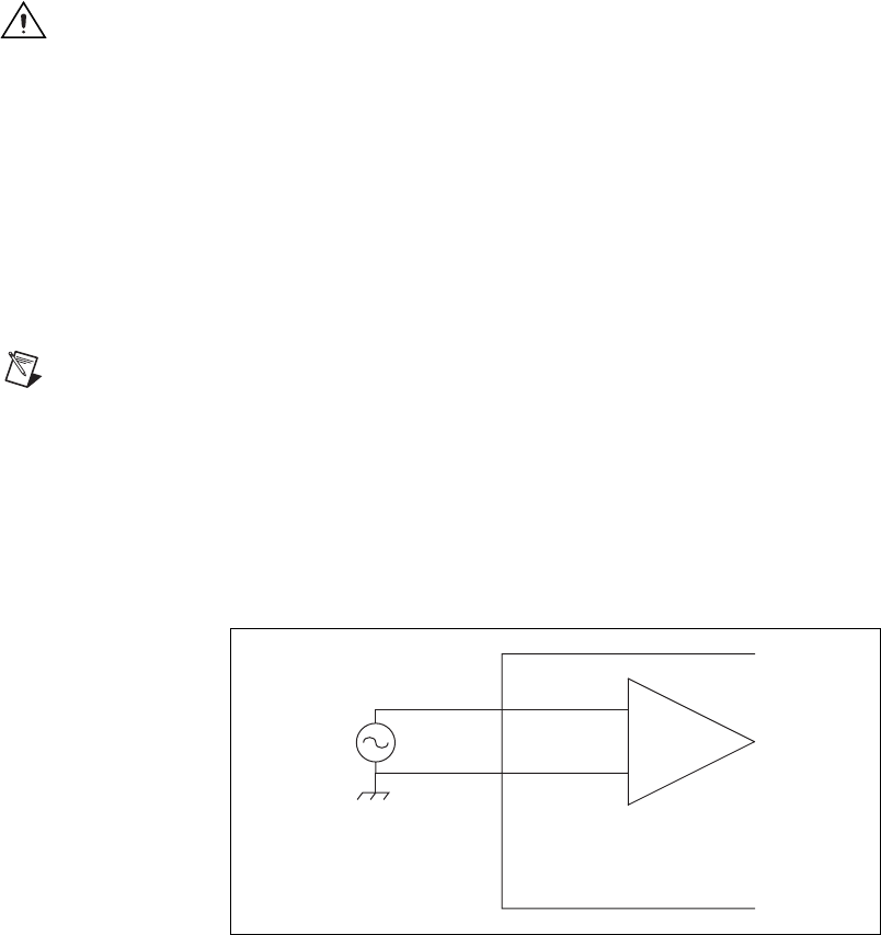
Figure 2-1 illustrates how to connect a ground-referenced signal source to
an SCXI-1141/1142/1143 module channel.
Figure 2-1. Ground-Referenced Signal Connection
IN–
IN+
SCXI-1141/1142/1143


