


Chapter 4 Theory of Operation
© National Instruments Corporation 4-5 SCXI-1141/1142/1143 User Manual
Lowpass Filters
The SCXI-1141/1142/1143 module filters are 8th-order elliptic, Bessel,
and Butterworth lowpass filters, respectively. These filters are a hybrid of
a switched-capacitor and a continuous-time architecture, thus providing
good cutoff frequency control while avoiding the sampling errors found in
conventional switched-capacitor designs. To better acquaint you with these
filters, this section describes what the filters do and presents examples of
how to use them on the SCXI-1141/1142/1143 module.
Filter Theory
Filters are generally grouped into one of five classifications—lowpass,
highpass, bandpass, bandstop, and all-pass. These classifications refer
to the frequency range (the passband) of signals that the filter is intended
to pass from the input to the output without attenuation. Because the
SCXI-1141/1142/1143 modules use a lowpass filter, this discussion is
limited to lowpass filters.
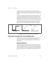
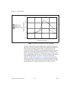
The ideal lowpass filter does not attenuate any input signal frequency
components in the passband, which is defined as all frequencies below the
cutoff frequency. The ideal lowpass filter completely attenuates all signal
components in the stopband, which includes all frequencies above the
cutoff frequency. The ideal lowpass filter also has a phase shift that is linear
with respect to frequency. This linear phase property means that signal
components of all frequencies are delayed by a constant time independent
of frequency, thereby preserving the overall shape of the signal.
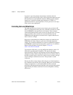
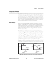
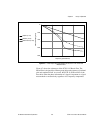
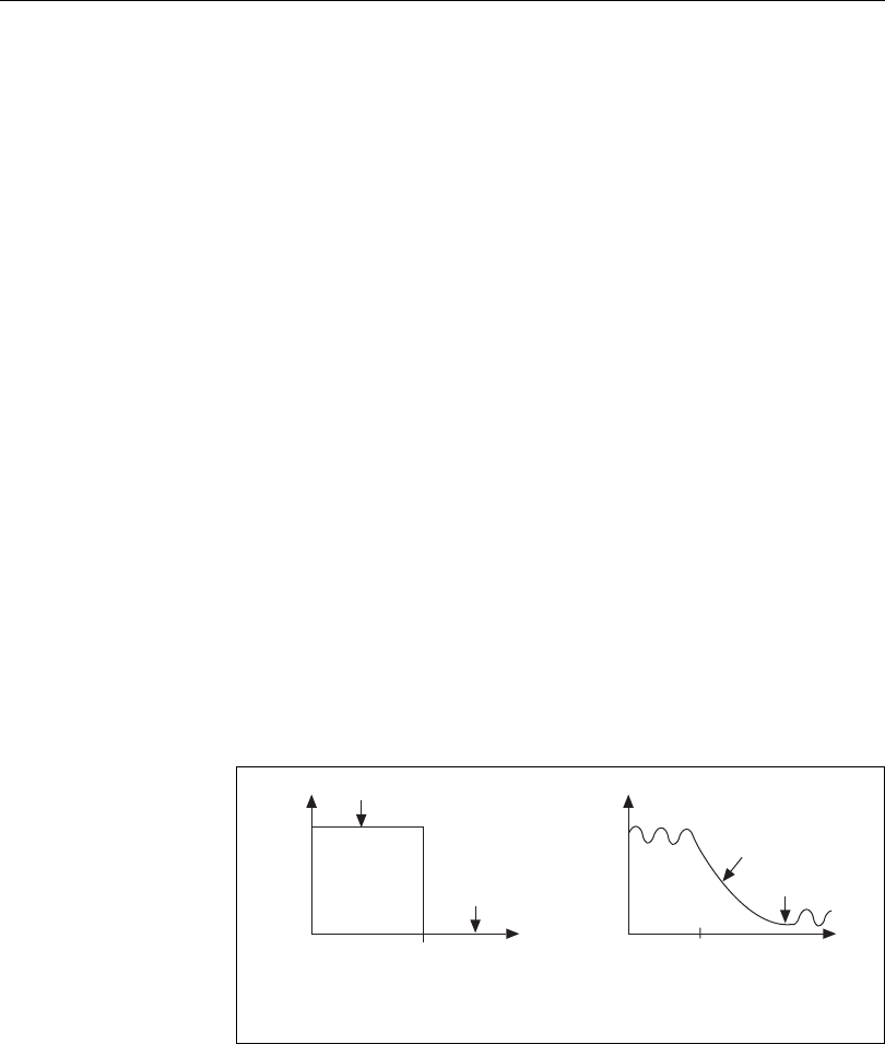
In practice, real filters can only approximate the characteristics of an ideal
filter. Figure 4-2 compares the attenuation of a real filter and an ideal filter.
Figure 4-2. Ideal and Real Lowpass Filter Transfer Function Characteristics
Passband
Stopband
Gain
Frequency
a. Ideal b. Real
f
c
Passband
Stopband
Gain
Frequency
f
c
Transition
Region