


Chapter 2 Configuring and Installing the SCXI Chassis
SCXI Chassis User Manual 2-4 ni.com
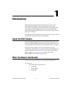
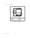
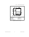
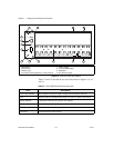
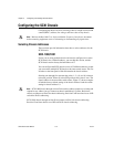
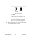
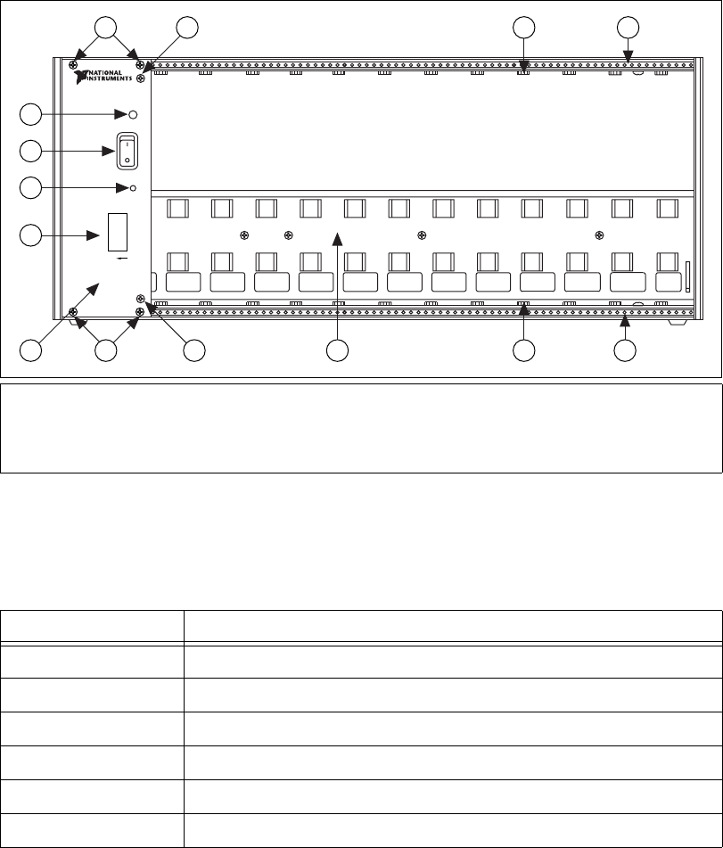
Figure 2-3. SCXI-1001 Front View Diagram
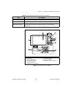
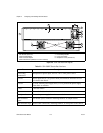
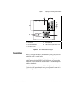
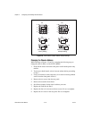
Tables 2-2 and 2-3 describe the rear view items shown in Figures 2-4, 2-5,
and 2-6.
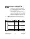
1 Address DIP Switches
2 Reset Button
3 Power Switch
4 Indicator Light
5 Front Panel Screws (flathead on some revisions)
6 Front Panel Screws (early revisions only)
7 Module Guides
8 Front Threaded Strips
9 Backplane
10 Slot 0/Power Supply
Table 2-2. SCXI-1000/1001 Chassis Rear View Items
Item Description
Power entry module IEC receptacle for power input, voltage selection board, and fuse
Fuse Protects both you and the SCXI chassis in case of a fault in the chassis
Voltage tumbler Configures the chassis for the AC line voltage
Fan(s) Cools the chassis
Filter(s) Prevents dirt from contaminating the circuitry in the chassis
Fan screws Secure the fan(s) to the chassis
ON
1
2
3
4
5
ADDRESS
4
3
2
1
9 7 8
7 85 6
65
10