


Chapter 2 Configuring and Installing the SCXI Chassis
SCXI Chassis User Manual 2-6 ni.com
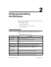
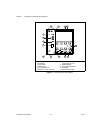
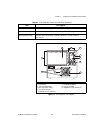
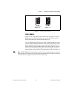
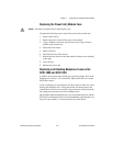
Figure 2-5. SCXI-1001 Rear View Diagram
1 Fans and Filters
2 Fan Screws (each fan)
3 Rear Threaded Strips
4 Rear Connector Space
5 Rear Panel Screws (flathead on some revisions)
6 Voltage Tumbler
7 Power Entry Module
8 Fuse (concealed)
9 Backplane Fuses (behind fan)
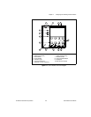
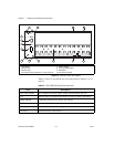
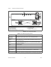
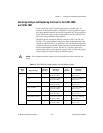
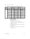
Table 2-3. SCXI-1000DC Chassis Rear View Items
Item Description
Power entry
connector J1
Receptacle for power input; uses a 9.5 to 16 VDC power source
Fuse F1 Power input fuse (6.3 A), protects both you and the SCXI chassis in case
of a fault in the chassis
Fuse F2 +5 VDC internal power supply fuse (3.15 A), protects the power supply
from shorts on modules
Fan(s) Cools the chassis
Fan screws Secure the fan(s) to the chassis
Backplane fuses Protect the power supply from shorts on modules
Rear connector
space
For module space, connector mounting brackets, or adapter boards
Rear threaded strips Secure cable connections, mounting brackets, or filler panels to the chassis
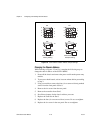
120Vac
3
4
8
6
7
1
9
1
5
2
5