Chapter 5 Signal Connections
© National Instruments Corporation 5-7 7344/7334 Hardware User Manual
Encoder Signals
The 7344/7334 controller offers four channels of single-ended quadrature
encoder inputs. All National Instruments power drives and UMI
accessories provide built-in circuitry that converts differential encoder
signals to single-ended encoder signals. Each channel consists of a
Phase A, a Phase B, and an Index input, as described in the following
sections.
Encoder<1..4> Phase A/Phase B
The encoder inputs provide position and velocity feedback for absolute
and relative positioning of axes in any motion system configuration.
If an encoder resource is not needed for axis control, it is available for other
functions including position or velocity monitoring, digital potentiometer
encoder inputs, or as a master encoder input for master/slave (electronic
gearing) applications.
The encoder channels (Encoder <1..4>) are implemented in an FPGA
and are high performance with extended input frequency response and
advanced features such as high-speed position capture inputs and
breakpoint outputs. The encoders have a maximum count frequency of
20 MHz.
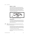
An encoder input channel converts quadrature signals on Phase A and
Phase B into 32-bit up/down counter values. Quadrature signals are
generated by optical, magnetic, laser, or electronic devices that provide
two signals, Phase A and Phase B, that are 90° out of phase. The leading
phase, A or B,determines the direction of motion. The four transition states
of the relative signal phases provide distinct pulse edges that cause count
up or count down pulses in the direction determined by the leading phase.
A typical encoder with a specification of N (N = number) lines per unit
of measure (revolutions or linear distance) produces 4 × N quadrature
counts per unit of measure. The count is the basic increment of position
in FlexMotion systems.
Note
Determine quadrature counts by multiplying the encoder resolution in encoder lines
by 4. The encoder resolution is the number of encoder lines between consecutive encoder
indexes (marker or Z-bit). If the encoder does not have an index output, the resolution
would be referred to as lines per revolution, or lines per unit of measure (inch, centimeter,
millimeter, and so on).


