


FP-PWM-520 and cFP-PWM-520 14 ni.com
Mechanical Dimensions
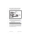
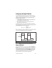
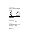
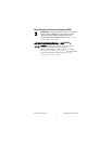
Figure 5 shows the mechanical dimensions of the FP-PWM-520
installed on a terminal base. If you are using the cFP-PWM-520,
refer to your Compact FieldPoint controller user manual for the
dimensions and cabling clearance requirements of the Compact
FieldPoint system.
Figure 5. FP-PWM-520 Mechanical Dimensions
Power Requirements
Power from network module ............1 W
Isolation Voltage
Isolation voltage is verified by a dielectric withstand test.
Channel-to-ground isolation
Continuous .................................250 V
rms
, Measurement
Category II
Dielectric withstand....................2,300 V
rms
, 5 s max
Channel-to-channel isolation............None
Environmental
FieldPoint modules are intended for indoor use only. For outdoor
use, they must be mounted inside a sealed enclosure.
Operating temperature ......................–40 to 70 °C
Storage temperature..........................–55 to 85 °C
Humidity...........................................10 to 90% RH,
noncondensing
Maximum altitude.............................2,000 m
Pollution Degree...............................2
109.5 mm
(4.31 in.)
91.44 mm
(3.60 in.)
107.19 mm
(4.22 in.)