


FP-PWM-520 and cFP-PWM-520 6 ni.com
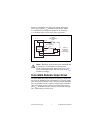
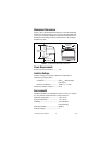
In the ON state, the effective resistance between V
OUT
and V
SUP
causes a voltage drop between the external supply voltage and the
output voltage. For example, if the external supply voltage is 5 V
and the output current is 1 A, calculate the output voltage as
follows:
5 V – (1 A × R
ON
) = V
OUT
where R
ON
is the ON resistance and V
OUT
is the output voltage.
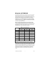
Refer to the Specifications section for the value of the ON
resistance.
Short-Circuit Protection
If the protection circuitry detects a short-circuit condition on an
output channel, it disables the output. If the protection circuitry
disables an output that would otherwise be in the ON state, the
status indicator for that channel is still lit, but the output transistor
is turned off.
Detecting a Short-Circuit Condition
To determine whether a channel is in a short-circuit condition,
complete the following steps:
1. In FieldPoint software, set the duty cycle to 100% for the
channel in question. Refer to the Configuring the Output
Channels section for more information about configuring the
duty cycle.
2. Measure the voltage between the V
OUT
and V
SUP
terminals for
that channel.
Under normal load conditions, the V
OUT
-to-V
SUP
voltage is
less than 1 V when the output is ON continuously. Any voltage
higher than 1 V indicates a short circuit. Typically, the
V
OUT
-to-COM voltage is almost zero if the protection circuitry
is activated.
Resetting a Channel in a Short-Circuit Condition
To reset a channel in a short-circuit condition, determine the cause
of the condition and disconnect the load from the channel. The
channel resets automatically when the load is removed.
Alternatively, if completely removing the channel load is not
convenient, reset the channel in any of the following ways:
• In FieldPoint software, set the duty cycle to 0%. The channel
resets immediately.