


Chapter 2 Hardware Installation and Configuration
© National Instruments Corporation 2-5 FBUS-HSE/H1 LD User Manual
Cabling
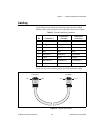
If you build your own cables, the following table shows the standard
Ethernet cable wiring connections for both normal and crossover cables.
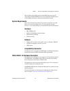
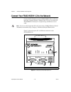
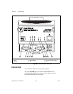
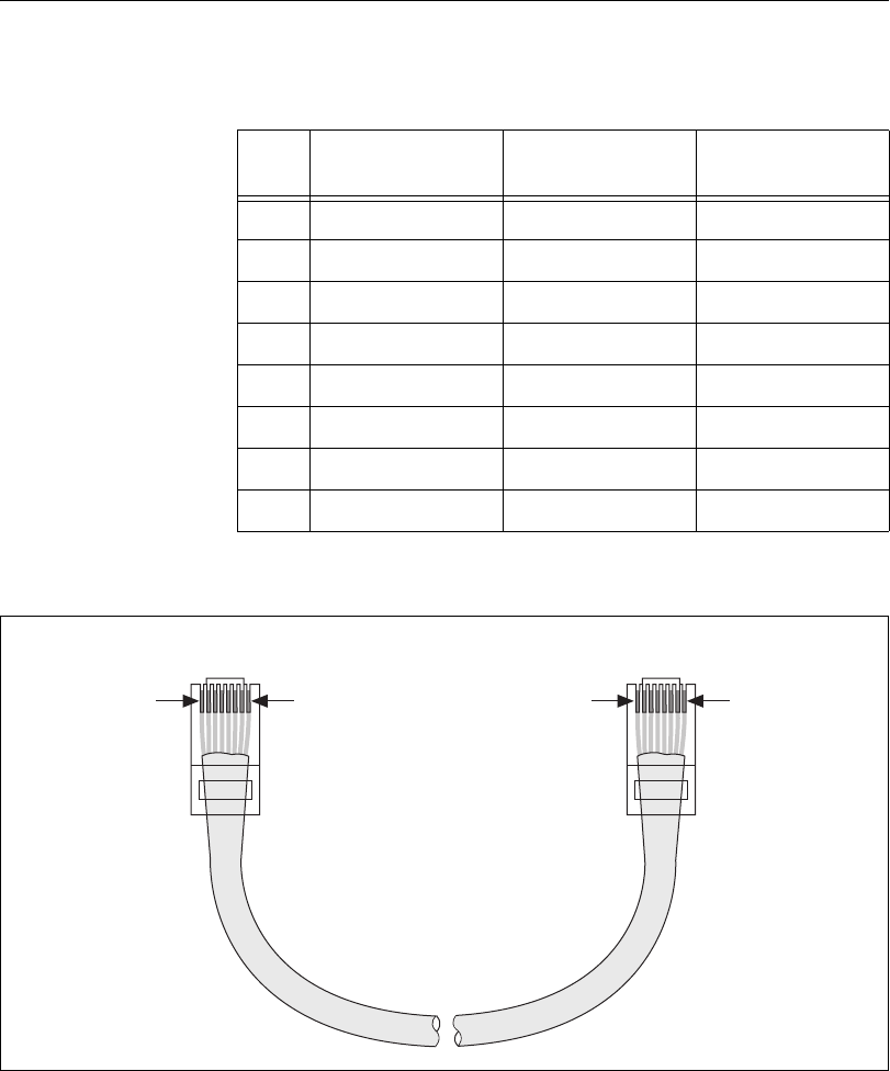
Figure 2-5 shows the connector pinouts for Fieldbus Ethernet cables.
Figure 2-5. Ethernet Cable Pinouts
Table 2-1. Ethernet Cable Wiring Connections
Pin Connector 1
Connector 2
(Normal)
Connector 2
(Crossover)
1 White/Orange White/Orange White/Green
2 Orange Orange Green
3 White/Green White/Green White/Orange
4 Blue Blue Blue
5 White/Blue White/Blue White/Blue
6 Green Green Orange
7 White/brown White/Brown White/Brown
8 Brown Brown Brown
Connector 1 Connector 2
Pin 1
Pin 1 Pin 8Pin 8