


Chapter 2 Hardware Installation and Configuration
© National Instruments Corporation 2-7 FBUS-HSE/H1 LD User Manual
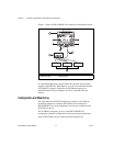
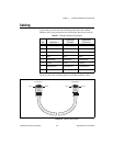
Connect Power to the FBUS-HSE/H1 LD
Each FBUS-HSE/H1 LD on your network requires an 11-30 VDC power
supply.
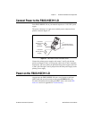
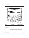
The power connector is a 6-pin screw terminal power connector whose
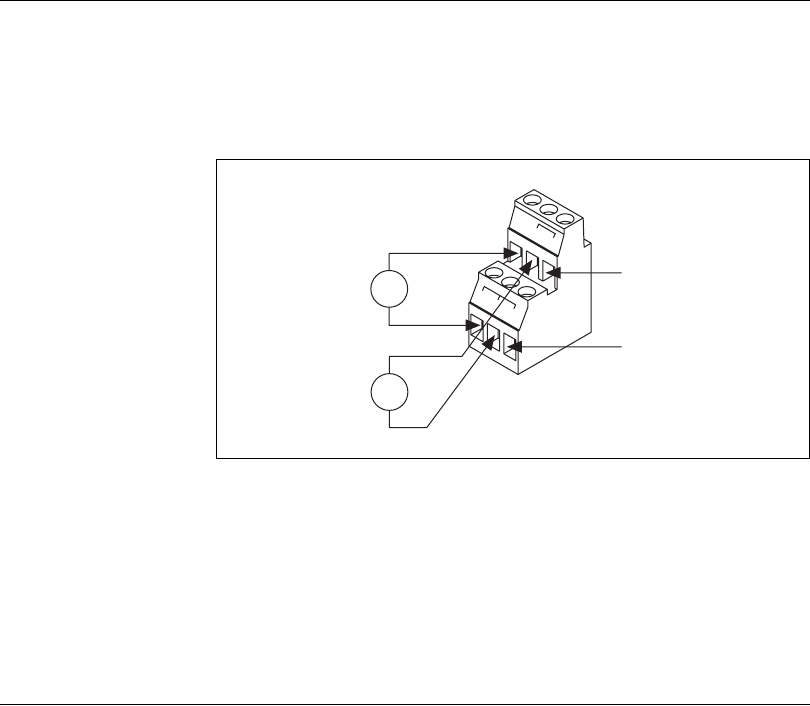
pinout is shown in Figure 2-7.
Figure 2-7. FBUS-HSE/H1 Power Connector Pinout
Connect the primary power supply to the center V and C pair with the
positive and negative wires on your power cable in the V and C terminals,
respectively. You can connect an optional backup power supply to the left
V and C pair. The right V and C pair provides the same power supply as the
primary power supply.
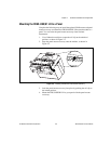
Power on the FBUS-HSE/H1 LD
At power-up, the FBUS-HSE/H1 LD runs a set of power-on self tests
(POST) that take several seconds and the green POWER LED is lit.
For more information about reading the POST status, refer to the LED
Indicators section of Appendix B, Troubleshooting.
v
v
v
c
c
c
11-30 VDC
Backup Power
Supply
(Optional)
+
–
+
–
11-30 VDC
Primary Power
Supply
V
C
To Adjacent Device
(Optional Connection)