


3
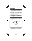
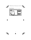
4. Add terminal bases to the DIN rail with their local bus
connectors firmly mated to the FP-1000 local bus connector.
The FP-1000 is shipped with a protective cover over the local
bus connector. Remove this protective cover, and place it over
the local bus connector of the last terminal base in the stack.
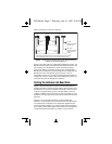
Figure 3 shows an installed FP-1000 network module.
Figure 3. Installed Network Module
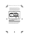
Network Connection
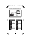
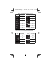
Connect the FP-1000 to a host computer using the 9-position DSub
RS-232 connector on the FP-1000. Connect the RS-232 port of the
FP-1000 to the RS-232 port on your computer using a male-to-
female “straight-through” cable. Do not use a “null modem” cable
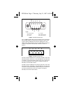
(usually female-to-female). For reference, the pinout of the
RS-232 connector on the FP-1000 is shown in Figure 4.
Protective
Cover
Local Bus Connectors
Firmly Mated
Rail Snap
Locked
DIN
Rail
FP1000.fm Page 3 Thursday, July 31, 1997 8:49 AM