


5
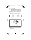
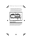
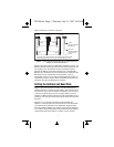
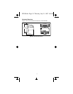
These connections are shown in Figure 6.
Figure 6. Typical Signal Connections with One FP-1000 Connected to
Multiple FP-1001 Network Modules
Figure 6 also shows the use of 120 Ohm termination resistors. An
RS-485 network must be terminated at each end of the network, but
not anywhere else. Termination resistors should be installed
between the RX pair and between the TX pair of the FP-1000
RS-485 port. Termination resistors should also be installed on the
RS-485 port of the last FP-1001 on the network. A pair of
terminating resistors are provided with each network module. To
install them, twist the resistor leads with the RS-485 signal wires
and insert them into the RS-485 port terminals.
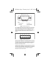
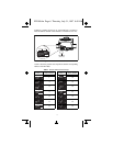
Setting the Address and Baud Rate
Figure 7 shows the 8-position switch on the FP-1000 network
module. Switches 1-5 set the network address, and switches 6-8 set
the baud rate. Every network module connected to one serial port
of the host computer must be given a unique address, however
modules on different serial ports may have the same address. Every
module on one serial port of the host computer must have the same
baud rate.
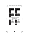
Switches 1-5 set the network address of the FP-1000. The
addresses of the terminal bases connected to the network module
are automatically configured to be sequentially higher than the
network module’s address. For example, if the network module is
set to address 20, the I/O module in the terminal base immediately
connected the network module is at address 21, the next I/O
To Host
Computer's RS-232
Receive Input
From Host
Computer's RS-232
Transmit Output
Ground
FP-1001 FP-1001 FP-1000
120Ω
TX
RX
TX RX
RX TX
120Ω
120Ω
120Ω
Connect the TX outputs of the FP-1001 to the RX inputs of the FP-1000,
and the RX inputs of the FP-1001 to the TX outputs of the FP-1000.
FP1000.fm Page 5 Thursday, July 31, 1997 8:49 AM