


4
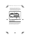
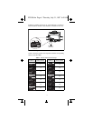
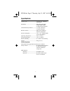
Figure 4. RS-232 Connector Pinout
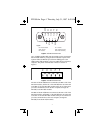
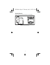
Up to 24 additional FP-1001 network modules can be connected to
this FP-1000 module by using the built in RS-485 repeater. This
repeater makes the RS-485 port of the FP-1000 appear to the
additional FP-1001 modules as if it were an RS-485 port of the host
computer. The pinout of the RS-485 connector is shown in
Figure 5.
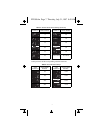
Figure 5. RS-485 Connector Pinout
The TX+ of the FP-1000 must be connected to the RX+ of all of the
FP-1001 modules, and the TX- of the FP-1000 must be connected
to the RX- of all of the FP-1001 modules. This pair of connections
provides communication from the host computer, through the
FP-1000, to the FP-1001 modules.
The RX+ of the FP-1000 must be connected to the TX+ of all of the
FP-1001 modules, and the RX- of the FP-1000 must be connected
to the TX- of all of the FP-1001 modules. This pair of connections
provides communication to the host computer, through the
FP-1000, from the FP-1001 modules.
GND
NC
RX
TX
NC
RTS
NC
DSR
NC
54321
9876
NC = Not Connected
GND = Ground
RX = Recieve
TX = Transmit
RTS = Request to Send
DSR = Data Set Ready
Legend:
RX–
RX+
TX–
TX+
GND
12345
FP1000.fm Page 4 Thursday, July 31, 1997 8:49 AM