


© National Instruments Corporation 4-1 GPIB-100A User Manual
Chapter 4
Theory of Operation
Diagrams
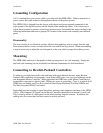
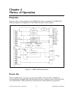
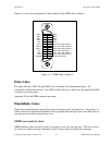
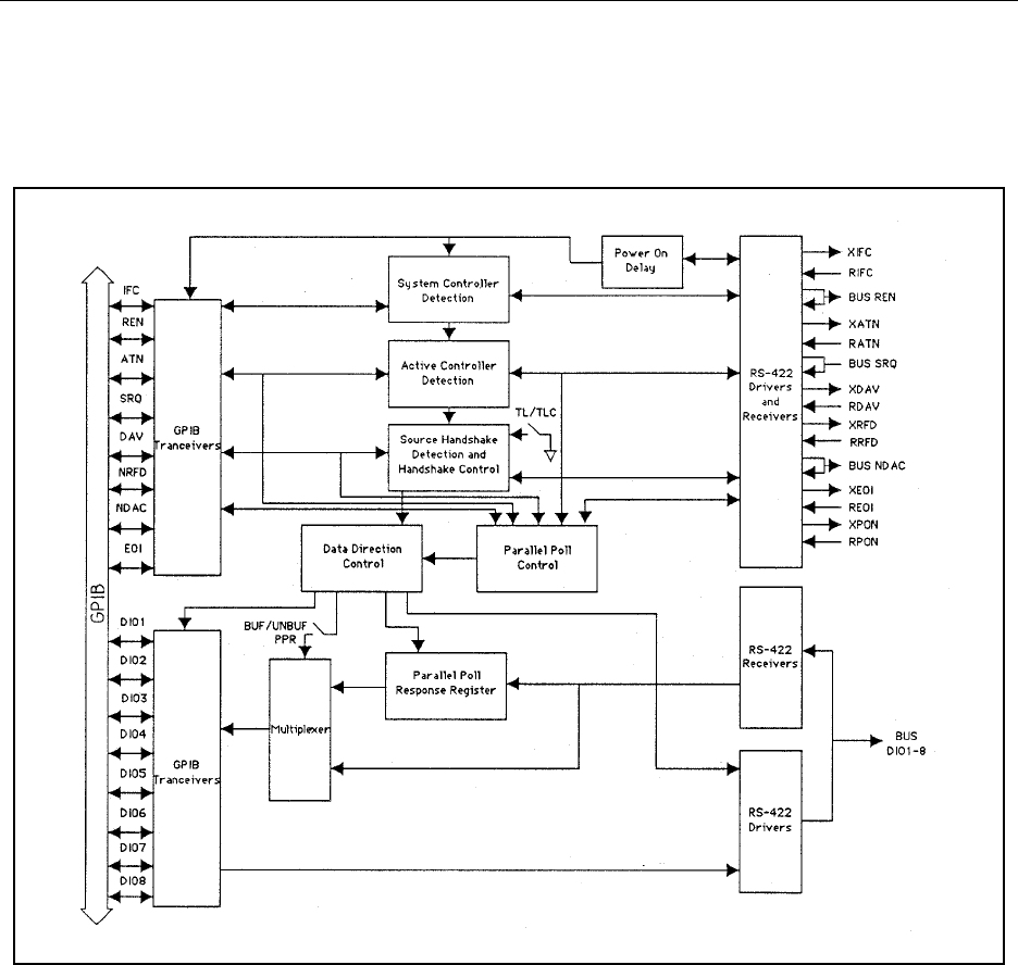
Figure 4-1 shows a block diagram for the GPIB-100A. Refer to Appendix B for GPIB-100A
schematic diagrams and Appendix C for the GPIB-100A parts locator diagram.
Figure 4-1. GPIB-100A Block Diagram
Power-On
When the GPIB-100A is powered on, a reset pulse (PON) created by U48F, U28A/D and
associated Register/Capacitor Delay (RCD) network directly or indirectly clears all flip-flops (FFs)
to an initialized state. PON remains active until both units in the extension are powered on.