


Operation of the GPIB Appendix A
GPIB-100A User Manual A-2 © National Instruments Corporation
The role of the GPIB Controller can also be compared to the role of the computer's CPU, but a
better analogy is to the switching center of a city telephone system.
The switching center (Controller) monitors the communications network (GPIB). When the
center (Controller) notices that a party (device) wants to make a call (send a data message), it
connects the caller (Talker) to the receiver (Listener).
The Controller usually addresses a Talker and a Listener before the Talker can send its message to
the Listener. After the message is transmitted, the Controller usually unaddresses both devices.
Some bus configurations do not require a Controller. For example, one device may only be a
Talker (called a Talk-only device) and there may be one or more Listen-only devices.
A Controller is necessary when the active or addressed Talker or Listener must be changed. The
Controller function is usually handled by a computer.
System Controller and Active Controller
Although there can be multiple Controllers on the GPIB, only one Controller at a time is Active
Controller or Controller-in-Charge (CIC). Active control can be passed from the current Active
Controller to an idle Controller. Only one device on the bus, the System Controller, can make
itself the Active Controller.
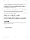
GPIB Signals
The interface bus consists of 16 signal lines and 8 ground return or shield drain lines. The 16
signal lines are divided into three groups:
• 8 data lines
• 3 handshake lines
• 5 interface management lines