


Appendix A Operation of the GPIB
© National Instruments Corporation A-3 GPIB-100A User Manual
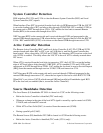
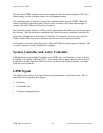
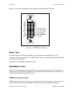
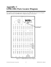
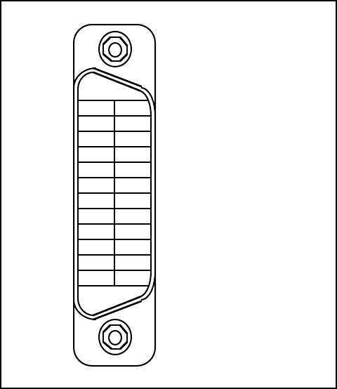
Figure A-1 shows the arrangement of these signals on the GPIB cable connector.
DIO1*
DIO2*
DIO3*
DIO4*
EOI*
DAV*
NRFD*
NDAC*
IFC*
SRQ*
ATN*
SHIELD
DIO5*
DIO6*
DIO7*
DIO8*
REN*
GND (TW PAIR W/DAV*)
GND (TW PAIR W/NRFD*)
GND (TW PAIR W/NDAC*)
GND (TW PAIR W/IFC*)
GND (TW PAIR W/SRQ*)
GND (TW PAIR W/ATN*)
SIGNAL GROUND
1
2
3
4
5
6
7
8
9
10
11
12
13
14
15
16
17
18
19
20
21
22
23
24
Figure A-1. GPIB Cable Connector
Data Lines
The eight data lines, DIO1 through DIO8, carry both data and command messages. All
commands and most data use the 7-bit ASCII or ISO code set, in which case the eighth bit, DIO8,
is unused or used for parity.
Appendix E lists the GPIB command messages.
Handshake Lines
Three lines asynchronously control the transfer of message bytes among devices. The process is
called a three-wire interlocked handshake and it guarantees that message bytes on the data lines are
sent and received without transmission error.
NRFD (not ready for data)
NRFD indicates when a device is ready or not ready to receive a message byte. The line is driven
by all devices when receiving commands and by Listeners when receiving data messages.