


NI 6509 User Guide and Specifications 14 ni.com
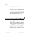
Signal Descriptions
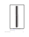
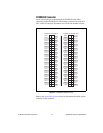
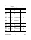
Table 3 lists the signals and descriptions for all signals available on the
NI 6509 device.
Table 3. NI 6509 Signal Descriptions
Pin Signal Name Description MSB LSB
1, 3, 5, 7, 9, 11, 13, 15 P2.<7..0> Bi-directional data lines for
port 2
P2.7 P2.0
2, 4, 6, 8, 10, 12, 14, 16 P5.<7..0> Bi-directional data lines for
port 5
P5.7 P5.0
17, 19, 21, 23, 25, 27,
29, 31
P1.<7..0> Bi-directional data lines for
port 1
P1.7 P1.0
18, 20, 22, 24, 26, 28,
30, 32
P4.<7..0> Bi-directional data lines for
port 4
P4.7 P4.0
33, 35, 37, 39, 41, 43,
45, 47
P0.<7..0> Bi-directional data lines for
port 0
P0.7 P0.0
34, 36, 38, 40, 42, 44,
46, 48
P3.<7..0> Bi-directional data lines for
port 3
P3.7 P3.0
49, 99 +5 V supply +5 volts; provides +5 V power
source
— —
50, 100 GND Ground; connected to the
computer ground signal
— —
51, 53, 55, 57, 59, 61,
63, 65
P8.<7..0> Bi-directional data lines for
port 8
P8.7 P8.0
52, 54, 56, 58, 60, 62,
64, 66
P11.<7..0> Bi-directional data lines for
port 11
P11.7 P11.0
67, 69, 71, 73, 75, 77,
79, 81
P7.<7..0> Bi-directional data lines for
port 7
P7.7 P7.0
68, 70, 72, 74, 76, 78,
80, 82
P10.<7..0> Bi-directional data lines for
port 10
P10.7 P10.0
83, 85, 87, 89, 91, 93,
95, 97
P6.<7..0> Bi-directional data lines for
port 6
P6.7 P6.0
84, 86, 88, 90, 92, 94,
96, 98
P9.<7..0> Bi-directional data lines for
port 9
P9.7 P9.0