


NI 6509 User Guide and Specifications 8 ni.com
Digital Filtering Example
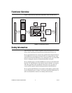
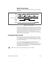
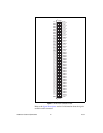
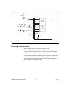
Figure 2 shows a filter configuration with an 800 ns filter interval (400 ns
filter clock).
Figure 2. Digital Filtering Example
In periods A and B, the filter blocks the glitches because the external signal
does not remain steadily high from one rising edge of the filter clock to the
next. In period C, the filter passes the transition because the external signal
remains steadily high. Depending on when the transition occurs, the filter
may require up to two filter clocks—one full filter interval—to pass a
transition. The figure shows a rising (0 to 1) transition. The same filtering
applies to falling (1 to 0) transitions.
Programmable Power-Up States
At power-up, the output drives on the NI 6509 are disabled. All lines are
user-configurable for high-impedance input, high output, or low output.
User-configurable power-up states are useful for ensuring that the NI 6509
powers up in a known state.
To use MAX (recommended) to program the power-up states, select
the device and click the Properties button. Refer to the software
documentation for information about how to program the power-up states
using NI-DAQ with LabVIEW or other National Instruments application
development environments (ADEs).
Note The response time of programmable power-up states is 400 ms.
External
Signal
External
Signal
Sampled
Filter
Clock
Sample Clock (100 ns)
Filtered
Signal
HHHHH
HLLHH
HLLHH
A
B
C