


© National Instruments Corporation 15 NI 6509 User Guide and Specifications
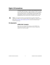
Power Connections
Pins 49 and 99 supply +5 V power to the I/O connector. The I/O connector
power has a fuse for overcurrent protection. This fuse is not customer
replaceable. If the fuse is blown, return the device to NI for repair.
Caution Do not connect the +5 V power pin directly to ground or to any other voltage
source on any other device. Doing so may permanently damage the NI 6509 device and the
computer.
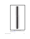
Signal Connections
The maximum input logic high and output logic high voltages assume a
Vcc supply voltage of 5 V. The absolute maximum voltage rating is –0.5 to
+5.5 V with respect to GND. Refer to the Specifications section for detailed
information.
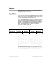
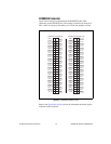
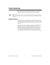
Figure 5 shows an example of signal connections for three typical digital
I/O applications. Port 0 is configured for digital output, and port 7 is
configured for digital input. Digital input applications include receiving
TTL signals and sensing external device states such as the state of the
switch in the figure. Digital output applications include sending TTL
signals and driving external devices such as the LED shown in the figure.