


NI 9215 Operating Instructions and Specifications 12 ni.com
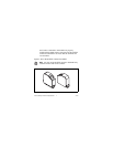
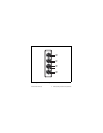
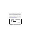
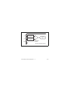
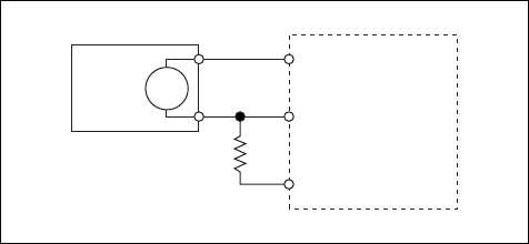
To connect floating differential signals to the NI 9215 with screw
terminal, you must connect the negative lead of the signal to COM
through a 1 MΩ resistor to keep the voltage source within the
common-mode voltage range, as shown in Figure 5. If the voltage
source is outside of the common-mode range, then the NI 9215
does not read data accurately. The NI 9215 with BNC has internal
circuitry that keeps the voltage source within the common-mode
range. For more information about the common-mode voltage
range, refer to the Specifications section.
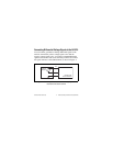
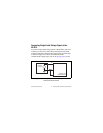
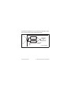
Figure 5. Connecting a Floating Differential Voltage Signal to the
NI 9215 with Screw Terminal
1 MΩ
Resistor
NI 9215 with
Screw Terminal
AI+
AI–
COM
Voltage
Source
+
–