


NI 9235/9236 14 ni.com
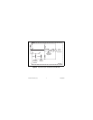
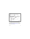
Shunt calibration simulates strain input by changing the resistance
of an arm in the bridge by a known amount. By shunting, or
connecting, a large resistor across one arm of the bridge, a specific
change occurs in the bridge voltage ratio. With the connected
sensor in a stable, typically unloaded, state, you can measure the
output of the bridge before and after the shunt calibration. You can
compare the measured reading change to the shunt calibration
output value to verify system setup or compensate for
quarter-bridge lead wire desensitization error. Refer to the
Specifications section for the shunt calibration output value. Visit
ni.com/info and enter lwcomp for information about lead wire
compensation.
Excitation Voltage
The NI 9235/9236 provides a constant excitation supply voltage to
each channel. The excitation supply provides sufficient output
current to power all eight channels at minimum resistance.
The excitation supply retains regulation even if one channel
experiences a gage short. If more than one channel has a gage
short, the excitation supply enters a current limit state and the
excitation voltage falls accordingly.