


NI sbRIO-960x 20 ni.com
During overvoltage conditions, high current flows through R1 and into the
protection diodes. High current causes internal heating in the posistor,
which increases the resistance and limits the current. Refer to the
Specifications section for current-limiting and resistance values.
Drive Strength
The sbRIO devices were tested with all 110 DIO channels driving 3 mA
DC loads, for a total of 330 mA sourcing from the FPGA. The FPGA uses
minimum 8 mA drivers, but the devices are not characterized for loads
higher than 3 mA.
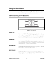
Signal Integrity
The sbRIO boards were designed with 60 Ω characteristic trace impedance.
The characteristic impedance of most IDC ribbon cables is 110 Ω, which is
grossly mismatched from the board. However, headers P2–P5 were
designed such that the signals are interwoven with ground
(signal/ground/signal/ground, etc.), which greatly improves the signal
integrity. This is sufficient for most applications
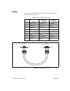
For the best possible signal integrity, use 3M
™
ribbon cable #3353, which
has a characteristic impedance of 65 Ω. This cable has a ground plane that
connects to the ground plane of the board at pin 1 and pin 50. The internal
ground plane of this cable also reduces noise and radiated emissions.
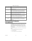
Using +5 V Power from 3.3 V DIO Headers P2–P5
Each of the four DIO headers has two pins to provide +5 V power for
external applications. This +5 V outputs are referenced to DGND on the
headers and are connected directly to the internal 5 V power plane of the
sbRIO device. The +5 V source has current limiting and overvoltage
clamps. Nevertheless, sudden current steps and noisy loads can inject
high-frequency transients into the power planes of the device. Such
transients can cause intermittent failures in the digital timing and lead to
unexpected behavior. Add filters and/or additional current limiting
between the external load and the +5 V output if the external load is not a
quiet, slowly ramping DC load. An LC filter of 6.8 μH and 100 μF per
200 mA load should be sufficient, but the OEM user is responsible for final
requirements and testing.
The sbRIO power supply is designed for a total of 2 A external load at 5 V.
This total includes 200 mA per installed C Series module. For example, if
three C Series modules are installed, only 2 A – (3 × 0.2) = 1.4 A is
available for use on headers P2–P5. Each pin on the headers is rated for 2 A,
but a typical 28 AWG ribbon cable is rated for only 225 mA per conductor.